Module 4.0
Amplifier Circuits
- Section 4.0 Introduction to Impedance and Bandwidth Control.
- • Recognise the need for changing the shape of an amplifier’s frequency response for:
- • Multiple Inputs.
- • De-Emphasis.
- Section 4.1 Input Compensation.
- • Describe typical input correction circuits.
- Section 4.2 Amplifier Controls.
- • Describe typical tone control circuits.
- • Baxandall Circuits & Tone Control ICs.
- Section 4.3 Amplifiers and Impedance.
- • Describe typical circuits for controlling impedance.
- • FET Input Circuits, Emitter Followers.
- • Darlington Outputs, Bootstrapping.
- Section 4.4 NFB Quiz.
- • Test your knowledge & understanding of impedance and tone control in audio amplifiers.
Introduction to Impedance and Bandwidth Control
Modified Response Curves
Previous modules have concentrated on producing a flat frequency response over the required audio frequency range. It is sometimes necessary however, to modify the flat response of an audio amplifier by making particular stages of the amplifier frequency dependent. This can be achieved by modifying either the response of one or more of the amplifier stages, or the response of a negative feedback path.
Fig. 4.0.1 shows (shaded green) stages where such modification will take place, the remaining stages having a flat response curve.

Fig. 4.0.1 Controlled Stages of an Audio Amplifier
Input Selection
The input select, or input compensation stage is used to match the input impedance of the amplifier to particular input device types, each of which may have different output impedances, signal levels and frequency ranges. The output of the select stage should therefore give fully compensated signal characteristics and a standard audio signal for any connected input device. It is possible however for a user to connect an input device that does not conform to the manufacturer's recommended specifications, especially as these may differ from one manufacturer to another. The most noticeable result is then, that a change in signal level may be heard when switching between different input devices.
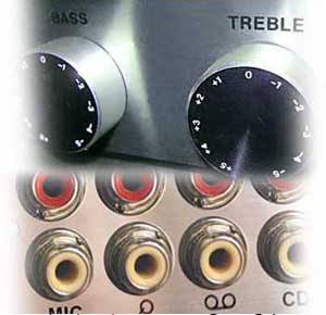
Tone Control
Tone control is used to boost or reduce the high or low frequencies of the audio signal to suit the user's requirements and/or the acoustics of listening environment. Placing this stage immediately before the power amplifier minimises any internally generated noise, which may occur if, for example a treble cut (HF reduction) circuit was followed by a number of full bandwidth amplifiers.
Modifying Input and Output Impedance.
The importance of an amplifier’s input and output impedance is discussed in AC Theory Module 7, and using NFB to control impedance is described in Amplifiers Module 3.2.
This module therefore describes some typical circuits used to control the values of input and output impedance and frequency characteristics of amplifier circuits.


