Class A Power Amplifiers
- After studying this section, you should be able to understand:
- The limitations due to the efficiency of class A power amplifiers.
- • Efficiency of class A
- • Effects on power supply requirements.
- Transformer coupled Class A power output stages.
- • The effect of an inductive load on Vpp.
- • Impedance matching with tranformer coupling.

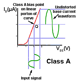
Fig 5.2.1 Class A Bias
Amplifier Classes
The Class A Common Emitter Amplifier described in Amplifier Module 1, Module 2 and Module 3 has some excellent properties that make it useful for many amplification tasks, however its use as a power amplifier is limited by its poor efficiency. Although Class A may be used for power output stages (usually low to medium power), it is less used for higher power output stages, as more efficient classes of amplifier such as Classes B, AB or even classes D, E, F, G and H are available.
The classes A, B, AB and C refer to the way the amplifiers are biased, although class C is mainly used in oscillator circuits. Classes D to H are used in switch mode amplifiers where power is saved by having the output transistors switched rapidly between fully on and fully off. In either of these states the transistor is dissipating little or no power.
Class A Power Amplifiers
The purpose of class A bias is to make the amplifier relatively free from distortion by keeping the signal waveform out of the region between 0V and about 0.6V where the transistor’s input characteristic is non linear. Class A design produces good linear amplifiers, but are wasteful of power. The output power they produce is theoretically 50%, but practically only about 25 to 30%, compared with the DC power they consume from the power supply.
Class A power amplifiers use the biasing method illustrated in Fig. 5.2.1. This method causes a standing bias current to be flowing during the whole waveform cycle, and even when no signal is being amplified. The standing bias current (the Quiescent Current) is sufficient to make the collector voltage fall to half the supply voltage, and therefore power (P = IC x VCC/2) is being dissipated by the transistor whether any signal is being amplified or not. This was not a great problem in class A voltage amplifiers, where the collector current was very small, but in power amplifiers output currents are thousands of times larger, so efficient use of power is crucial.
Transformer Coupled Class A Output
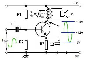
The circuit shown in fig 5.2.2 is a class A power output stage, but its efficiency is improved by using an output transformer instead of the resistor as its load.

Fig 5.2.2 Basic Class A Power Amplifier
The transformer primary winding has high apparent impedance (ZP) at audio frequencies because of the action of the transformer in ‘magnifying’ the impedance of the loudspeaker. As shown by the formula:
ZP = ZLS (NP/NS)2
The apparent impedance of the primary winding (ZP) will be the actual impedance of the loudspeaker (ZLS) multiplied by the square of the turns ratio.
Although the impedance of the transformer primary winding is high, its DC resistance (at 0Hz) is practically zero ohms. Therefore while a class A voltage amplifier might be expected to have a collector voltage of about half supply, a class A power amplifier will have a DC collector voltage approximately equal to the supply voltage (+12V in Fig. 5.2.2) and because of the transformer action, this allows a voltage swing of 12V above and below the DC collector voltage, making a maximum peak to peak signal voltage (Vpp) available of 24V.
With no signal, the quiescent collector current of the (medium power) output transistor may typically be about 50mA. When a signal is applied, the collector current will vary substantially above and below this level.
Class A power amplifiers, using the relatively linear part of the transistors characteristics are less subject to distortion than other bias classes used in power amplifiers, and although their inferior efficiency improves when output transformers are used, the introduction of a transformer can itself produce additional distortion. This can be minimised by restricting amplitude of the signal so as to utilise less than the full power of the amplifier, but even under optimum conditions the efficiency of class A presents problems. With substantially less than 50% of the power consumed from the supply going into the signal power supplied to the loudspeaker, the wasted power is simply produced as heat, mainly in the output transistor(s).
In large high power amplifiers class A is not practical. For example an amplifier used to produce 200W to a large loudspeaker system would need a 400W amplifier producing at its most efficient, 200W of wasted heat that must be dissipated by very large transistors and even larger heat-sinks if overheating, and subsequent component failure is to be avoided. Class A output stages are therefore used mainly in low to medium power output stages of 1 to 2 watt and below, such as domestic radio or TV receivers and headphone amplifiers.


