Module 1.0
Oscillator Basics
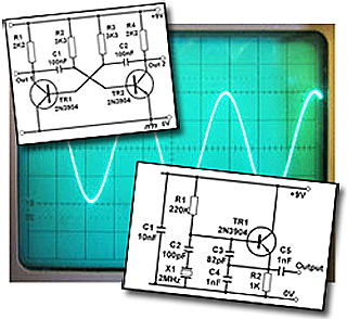
- Section 1.0 Oscillator Basics.
- • Typical oscillator types & applications.
- Section 1.1 Oscillator Operation.
- • Parts of an oscillator.
- • Positive feedback.
- • Conditions for oscillation.
- • Amplitude control.
- Section 1.2 Oscillator Basics Quiz
- • Test your knowledge of Oscillator basics
Introduction
These oscillator modules in Learnabout Electronics describe how many commonly used oscillators work, using discrete components and in integrated circuit form. Also learn how to build and test oscillators circuits yourself.
What is an Oscillator
An oscillator provides a source of repetitive A.C. signal across its output terminals without needing any input (except a D.C. supply). The signal generated by the oscillator is usually of constant amplitude.
The wave shape and amplitude are determined by the design of the oscillator circuit and choice of component values.
The frequency of the output wave may be fixed or variable, depending on the oscillator design.
Types of Oscillator

Fig. 1.0.1 Oscillator
(AC Source)
Circuit Symbol
Oscillators may be classified by the type of signal they produce.
- SINE WAVE OSCILLATORS produce a sine wave output.
- RELAXATION OSCILLATORS and ASTABLE MULTIVIBRATORS produce Square waves and rectangular pulses.
- SWEEP OSCILLATORS produce sawtooth waves.
Sine wave oscillators can also be classified by frequency, or the type of frequency control they use. RF (radio frequency) oscillators working at frequencies above about 30 to 50kHz use LC (inductors and capacitors) or Crystals to control their frequency. These may also be classified as HF, VHF, and UHF oscillators, depending on their frequency.
LF (low frequency) oscillators are generally used for generating frequencies below about 30kHz and are usually RC oscillators, as they use resistors and capacitors to control their frequency.
Square wave oscillators such as relaxation and astable oscillators may be used at any frequency from less than 1Hz up to several GHz and are very often implemented in integrated circuit form.
Sine Wave Oscillators.
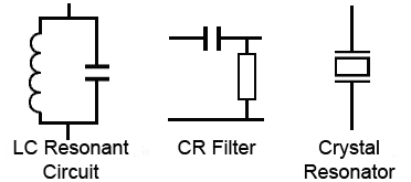
Fig. 1.0.2 Frequency Control Networks
These circuits ideally produce a pure sine wave output having a constant amplitude and stable frequency. The type of circuit used depends on a number of factors, including the frequency required. Designs based on LC resonant circuits or on crystal resonators are used for ultrasonic and radio frequency applications, but at audio and very low frequencies the physical size of the resonating components, L and C would be too big to be practical.
For this reason a combination of R and C is used to a control frequency. The circuit symbols used for these frequency control networks are shown in Fig. 1.0.2
LC oscillators
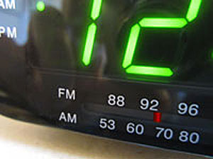
Inductors and capacitors are combined in a resonating circuit that produces a very good shape of sine wave and has quite good frequency stability. That is, the frequency does not alter very much for changes in the D.C. supply voltage or in ambient temperature, but it is relatively simple, by using variable inductors or capacitors, to make a variable frequency (tuneable) oscillator. LC oscillators are extensively used in generating and receiving RF signals where a variable frequency is required.
RC (or CR) oscillators
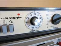
At low frequencies such as audio the values of L and C needed to produce a resonating circuit would be too large and bulky to be practical. Therefore resistors and capacitors are used in RC filter type combinations to generate sine waves at these frequencies, however it is more difficult to produce a pure sine wave shape using R and C. These low frequency sine wave oscillators are used in many audio applications and different designs are used having either a fixed or variable frequency.
Crystal oscillators
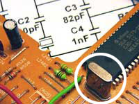
At radio frequencies and higher, whenever a fixed frequency with very high degree of frequency stability is needed, the component that determines the frequency of oscillation is usually a quartz crystal, which when subjected to an alternating voltage, vibrates at a very precise frequency. The frequency depends on the physical dimensions of the crystal, therefore once the crystal has been manufactured to specific dimensions, the frequency of oscillation is extremely accurate. Crystal oscillator designs can produce either sine wave or square wave signals, and as well as being used to generate very accurate frequency carrier waves in radio transmitters, they also form the basis of the very accurate timing elements in clocks, watches, and computer systems.
Relaxation oscillators

These oscillators work on a different principle to sine wave oscillators. They produce a square wave or pulsed output and generally use two amplifiers, and a frequency control network that simply produces a timing delay between two actions. The two amplifiers operate in switch mode, switching fully on or fully off alternately, and as the time, during which the transistors are actually switching, only lasts for a very small fraction of each cycle of the wave, the rest of the cycle they "relax" while the timing network produces the remainder of the wave. An alternative name for this type of oscillator is an "astable multivibrator", this name comes from the fact that they contain more than one oscillating element. There are basically two oscillators, i.e. ''vibrators'', each feeding part of its signal back to the other, and the output changes from a high to a low state and back again continually, i.e. it has no stable state, hence it is astable. Relaxation oscillators can be built using several different designs and can work at many different frequencies. Astables may typically be chosen for such tasks as producing high frequency digital signals. They are also used to produce the relatively low frequency on-off signals for flashing lights.
Sweep oscillators
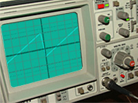
A sweep waveform is another name for a saw-tooth wave. This has a linearly changing (e.g increasing) voltage for almost the whole of one cycle followed by a fast return to the wave’s original value. This wave shape is useful for changing (sweeping) the frequency of a voltage-controlled oscillator, which is an oscillator that can have its frequency varied over a set range by having a variable ‘sweep’ voltage applied to its control input. Sweep oscillators often consist of a ramp generator that is basically a capacitor charged by a constant value of current. Keeping the charging current constant whilst the charging voltage increases, causes the capacitor to charge in a linear fashion rather than its normal exponential curve. At a given point the capacitor is rapidly discharged to return the signal voltage to its original value. These two sections of a saw-tooth wave cycle are called the sweep and the fly-back.


