Module 5.2
Phasors
- After studying this section, you should be able to describe:
- • Use of phasors to simplify complex waveform diagrams.
- • Relationship between waveforms and phasor diagrams.
- • Angular velocity and the radian.
A better way to analyse complex waveform diagrams
In discussing phase shifts between currents and voltages in ac circuits, diagrams showing multiple waveforms such as those in module 5.1 could be used, but this involves a lot of complex drawing of waveforms which would, in many cases, be hard to interpret, and even more difficult to take measurements from. If calculations involving these waveforms were needed the waveforms would also need to be accurately drawn to scale.
A much more convenient method is to replace the sine wave drawings with phasor diagrams. Making use of a few facts about a sine wave, provides a much simpler way to represent a wave.

Simplifying a Sine Wave
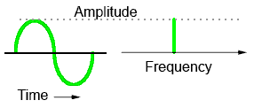
A sine wave has only one frequency, so this can be represented by simply choosing a suitable point on a horizontal line that represents a suitable range of frequencies .
The sine wave will have a particular amplitude, this can be represented by using a vertical line equal to the amplitude of the wave.
So the complex drawing af a sine wave shape can be simplified to just a couple of straight lines; one representing a frequency, and the other showing amplitude. The problem here however, is to draw a diagram that can represent a number of sine waves, each having the same frequency, but with different phase relationships to each other, which is where phasors are used.
Fig. 5.2.1 How a Phasor Relates to a Sine Wave
A phasor is a straight line drawn in such a way that its length is related to the amplitude of the sine wave represented, and its angular position relative to other phasors is related to the phase difference between the quantities.
The relationship between a phasor and a single sine wave is illustrated in fig 5.2.1. The phasor represented by the arrow is rotating in an anticlockwise direction about the centre origin point, describing the sine wave as it rotates.
Note that:
a. At any point in time, the length of the red dotted line represents the instantaneous value of the wave.
b. The length of the phasor represents the amplitude of the wave.
c. The angle of the phasor gives the phase of the waveform. Increments in phasor angle in the circular diagram are equivalent to time or angle increments along the horizontal axis of the waveform diagram. So with this addition of angular information, the phasor gives a relatively simple way to show the complex relationships that exist between sine waves in an ac circuit.
Angular Velocity.
As a phasor is rotating, the speed at which it rotates about the origin point will depend on the frequency (ƒ) of the wave represented. In one second the phasor will rotate through ƒ revolutions, or through ƒ x 360° (since one revolution = 360°).
In calculations involving such rotation, it is more common to use the angular unit RADIAN (rad.) where 360° = 2π rads. The phasor can therefore be said to rotate through 2πƒ radians per second. This is called the ANGULAR VELOCITY of the phasor, and is commonly represented by 2πƒ or alternatively by the symbol ω (omega).


