Module 5.4
Push-pull Driver Circuits
- After studying this section, you should be able to:
- Understand the need for push-pull driver circuits.
- • Driver transformers.
- Understand the operation of transistor phase splitters.
- • Phase splitter amplifiers.
- • Emitter-coupled phase-splitter.
- Know the principles of transformerless push-pull.
Driver Transformer

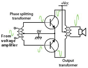
Fig 5.4.1 Phase splitting using
a driver transformer
When a pair of similar transistors (2 x NPN or 2 x PNP) are used in push-pull mode, it is necessary to supply their inputs with two identical anti-phase signals. This can be done by using a phase splitting transformer such as that shown in Fig. 5.4.1 to couple an audio voltage amplifier to the push-pull output transistors. An output transformer with a centre tapped primary winding re-combines the two half cycles of the output waveform, so that the loudspeaker is fed with the complete waveform by the transformer secondary. The output transformer also provides impedance matching so that maximum power is delivered from the amplifier to the loudspeaker.
Common Emitter Phase Splitter

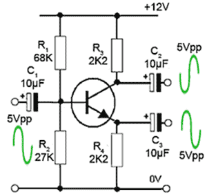
Fig 5.4.2 Phase splitting using
a transistor amplifier
An alternative method of providing anti-phase signals to the inputs of the output transistors is by using a transistor phase splitter stage (Fig. 5.4.2); this circuit is just like a standard class A voltage amplifier, except that two outputs are provided, with two equal value load resistors, one from the collector to supply and one from the emitter to ground. Notice that the emitter resistor is not decoupled, and therefore 100% negative feedback will be present, making the stage gain = 1. The maximum amplitude of the two output signals will each be slightly less than half the supply voltage (i.e. about 5Vpp each for a 12V supply). The purpose of this circuit is not to amplify, but simply to provide two equal and anti-phase signals.
Emitter Coupled (Long Tailed Pair) Phase Splitter

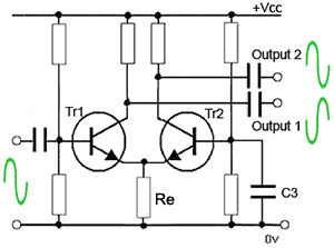
Fig 5.4.3 Emitter Coupled (Long Tailed Pair)
Phase Splitter
The phase splitter circuit illustrated in Fig. 5.4.3 is based on the emitter coupled, or long tailed pair differential amplifier, commonly found within integrated circuits. In this discrete component version the audio input is applied to the base of Tr1 while the base of Tr2 is held at a steady DC potential. No AC appears on the base of Tr2 due to the decoupling capacitor C3. Notice that both transistors share the same emitter resistor Re and two anti phase outputs are taken from the two collectors.
Operation
When the voltage at Tr1 base increases during the positive going half cycle of the input wave, the voltage at Tr1 collector will fall as the current through Tr1 increases. This increase in Tr1 current will tend to increase the voltage across the shared emitter resistor Re.
This rise in emitter voltage will also be seen at Tr2 emitter, and as the base of Tr2 is held at a steady potential the base/emitter potential of Tr2 will be reducing, tending to turn Tr2 off. The consequent fall in current through Tr2 will cause its collector voltage to rise; note that this rise is in anti phase to the fall in Tr1 collector voltage. The two collectors are 180° out of phase, and this condition continues throughout the whole cycle of the audio signal.
Provided that the current gain and temperature stability of the two transistors are perfectly matched, the rise in emitter current due to one transistor turning on will be exactly matched by the fall in current due to the other transistor turning off. Therefore the voltage across Re should remain constant and no AC signal will appear across Re. In practice this is not easy to achieve in discrete (individual components) circuits due to the spread in characteristics in individual transistors during manufacture. In integrated circuit manufacture all the transistors in the chip are fabricated on the same piece of silicon, under exactly the same conditions, so it is much easier to match the two transistors.
There are a number of closely matched transistor arrays available in IC form containing matched transistors available from manufacturers such as National Semiconductor, now part of Texas Instruments.


