Module 2.3
I.C. Voltage Regulators

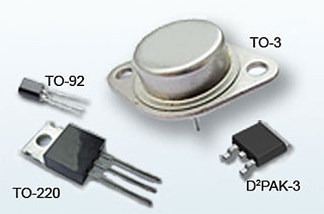
Fig. 2.3.1 Typical LM78xx Series Packages
- After studying this section, you should be able to:
- Recognise commonly used I.C. Voltage Regulators.
- In Relation to the 78xx series of Voltage Regulators:
- • Select appropriate decoupling components.
- • Understand the term ‘Dropout’.
- • Understand possible causes of IC failure & their prevention.
- • Understand methods of producing positive, negative & dual supplies.
The LM78Xxx Integrated Circuit (I.C.) Range
The availability of regulator circuits in I.C. form has greatly simplified power supply design, and since their introduction, the variety of designs, their power handling capacity and their reliability has steadily improved. Integrated circuit regulators are readily available in a variety of current and voltage ratings for shunt or series applications as well as complete switched mode types. It is now quite rare to find regulators in the truly discrete forms described in PSU Modules 2.1 to 2.3 but the popular 78Xxx types of regulator (where X indicates the sub type and xx represents the output voltage) use much the same principles, with enhanced circuitry, in an integrated form.
There are various ranges, in several package types available from many component manufacturers, some of which are shown in Fig. 2.4.1. The package choice is dependent space and performance requirements. Typical ranges are summarised in Table 1.
| Table 1 | ||||
|---|---|---|---|---|
| Range | Output Voltages (VOUT) | Maximum Current | Maximum Input Voltage | Typical Dropout Voltage |
| LM78Lxx | 5.0V, 6.2V, 8.2V, 9.0V, 12V, 15V | 100mA | 35V | VOUT + 1.7V |
| LM78Mxx | 5V, 12V, 15V | 500mA | 35V | VOUT + 2V |
| LM78xx | 5.0V, 5.2V, 6.0V, 8.0V, 8.5V, 9.0V, 12.0V, 15.0V, 18.0V, 24.0V | 1A | 35 or 40V dependent on type | VOUT + 2.5V |
Dropout Voltage
One of the important pieces of data published in data sheets on linear I.C. regulators is the devices dropout voltage. With any linear regulator, built with discrete components or integrated such as the 78 series, the output voltage is held steady for differing current flows by varying the resistance of the regulator, (actually by varying the conduction of a transistor as explained in Power Supplies Module 2.2).
For this reason two things must be true:
1. The output voltage must always be lower than the input voltage.
2. The greater the difference between the input and output voltages (given the same current) the more power must be dissipated in the regulator circuit, so the hotter it will get.
The dropout voltage for any regulator states the minimum allowable difference between output and input voltages if the output is to be maintained at the correct level. For example if a LM7805 regulator is to provide 5V at its output, the input voltage must be no lower than 5v +2.5V =7.5V.
However dropout voltage is not an absolute value, it may vary by about 1V depending on the current drawn from the output and the temperature at which the regulator is operating. It seems sensible therefore to allow a comfortable margin between the lowest possible input voltage and the minimum voltage allowable (the output voltage + the dropout voltage).
The maximum input voltage listed in table 1 shows that there is plenty of allowable difference between maximum and minimum input voltage, however it should be remembered that the higher the input voltage for a given output, the more power will need to be dissipated by the regulator. Too high an input voltage and power is wasted, this is bad for battery life in portable equipment and bad for reliability in high power equipment as more heat means a greater possibility of faults.
For example a LM7805 delivering 1A at 5V to a load means that the load is consuming 5Watts. If the input voltage is 8V the current through the regulator is still 1A, which is 8W; so the regulator is dissipating 8W − 5W = 3W. However if the input voltage is 20V for example, then the excess power that must be dissipated by the regulator is now 20V x 1A = 20W minus the 5W consumed by the load = 15W.
In modern linear I.C. regulators however, as well as protection against over current and over voltage protection, as described in PSU Module 2.3 there are additional thermal shut down circuits to prevent failure due to overheating, so that if power is excessive, rather than destroying the IC the output will fall to 0V until the IC has cooled.
Even at more sensible input voltages, regulator I.Cs. do develop considerable amounts of heat, therefore it is essential that excess heat is dissipated efficiently by the use of appropriate heat sinks. The criteria for using heat sinks is the same as that for power transistors, discussed in Amplifiers Module 5.1.
Complementing the 78xx series is the 79 series, which offers I.Cs. for commonly used negative supply voltages in a similar range of characteristics to the 78 series but with a negative voltage output.

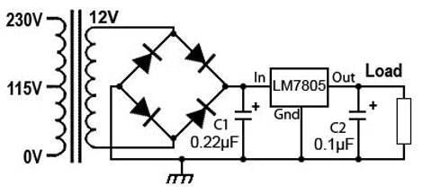
Fig. 2.3.2 Basic PSU Circuit Using a 7805 Linear Regulator I.C.
Reducing AC Ripple
Fig. 2.3.2 shows a series regulator I.C. and its connections. Notice that C1 and C2 are much smaller than would be found in discrete component power supply. A large reservoir capacitor is not necessary, as the regulating action of the I.C. will reduce the amplitude of any AC ripple (within its maximum input voltage range) to just a few millivolts at the output.
Ensuring Stability
C2 is no longer a traditional filter capacitor but is there to improve the transient response, protecting against sudden changes in mains or load conditions e.g. surges. The use of these capacitors, which with the values shown will be polarised tantalum types and although not strictly essential in all circuits, are recommended to ensure maximum stability, preventing any tendency of the I.C. to oscillate. They should be mounted as close as possible to the regulator, and the I.C. ground connection should be connected to 0V as physically close as possible to the ground connection of the load. These issues can be best accommodated when the regulator I.C. is used as a ‘point of load’ regulator, rather than (or as well as) a main regulator for the whole system power supply.
Reliability
The use of linear regulator I.Cs. has greatly improved the reliability of power supplies, but because these I.C.s are often located on plug in sub-panels with a system, there is a danger that damage may occur to the regulator I.C. (as well as to other components) if panels are inserted or removed whilst the main power supply is still live. This may be either because the system is still connected to the mains supply or because capacitors in the main supply are not fully discharged.
The reason is that when unplugging or connecting multi-way connectors there is no guarantee in which order individual pins are connected or disconnected, and this can lead to unexpected short circuit or open circuit faults occurring momentarily during the connection or disconnection process.

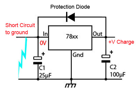
Fig. 2.3.3 Protection Diode Used With 7805 & Large Capacitors
To guard against this possibility several additional safeguards can be designed around the regulator circuitry to safeguard the I.C.
In some circuits electrolytic capacitors may be used for C1 and C2 as an alternative to using tantalum or polyester capacitors, but in this case the capacitance use will be considerably greater, 25µF or more. However, in circuits where C2 is 100µF or more, there is a possibility that if the input is shorted to ground, either temporarily (or permanently because of a fault) that the charge on C2 will cause a large current to flow back into the I.C. output terminal, damaging the I.C. To prevent this, a diode such as a 1N4002 can be connected across the I.C. as shown in Fig. 2.3.3 so that if, at any time the input terminal is at a lower potential than the output, the diode will conduct any charge at the output terminal to ground, rather than allowing the current to flow though the I.C.

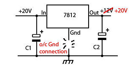
Fig. 2.3.4 Effect of Open Circuit Gnd Connection on a 7812 IC
If a circuit panel is unplugged whilst the supply is live it is possible that the ground connection to the I.C. may be disconnected momentarily before the input as indicated by Fig. 2.3.4. In such event the output terminal can rise to the voltage level of the unregulated input, which could cause damage to components being supplied by the regulator. Also if the panel is plugged in with power already present, the same situation, with the ground connection momentarily open circuit, then damage to the I.C. is likely.
As voltage regulators are generally fed from the main power supply, they can be susceptible to any mains borne voltage spikes as well as back e.m.f. voltage spikes from other parts of the circuit. Any positive voltage spikes greater than the maximum permitted input voltage (around 35V or 40V) or any negative spikes greater than -0.8V that have sufficient energy to cause substantial currents to flow are likely to damage the I.C. Some protection can be given by using a large value capacitor at the input terminal and/or making sure that likely causes of transients are minimised by using transient suppressors at the mains input and preventing back e.m.fs. as described in A.C. Theory Module 3.2.
Dual and Negative Supplies
Linear regulator I.C.s can also be used to provide regulated negative supplies using the LM79xx range of regulators are available in a similar range of voltages as the 78xx series but with negative outputs. They can be used for regulating negative supply or dual supply rails.


