Module 1.1
Amplifier Parameters
- After studying this section, you should be able to:
- Describe typical amplifier parameters.
- • Gain.
- • Frequency response.
- • Bandwidth.
- • Input impedance.
- • Output impedance.
- • Phase shift.
- • Feedback.
Describing an Amplifier
Any amplifier is said to have certain parameters. These are the particular properties that make the amplifier perform in a certain way, and so make it suitable for a given task. Typical amplifier parameters are described below.
Gain
The gain of an amplifier is a measure of the "Amplification" of an amplifier, i.e. how much it increases the amplitude of a signal. More precisely it is the ratio of the output signal amplitude to the input signal amplitude, and is given the symbol "A". It can be calculated for voltage (Av), current (Ai) or power (Ap), When the subscript letter after the A is in lower case this refers to small signal conditions, and when the subscript is in capitals it refers to DC conditions. The gain or amplification for the three differnt types of amplifiers can be described using the appropriate formula:
Voltage gain Av = Amplitude of output voltage ÷ Amplitude of input voltage.

Current gain Ai = Amplitude of output current ÷ Amplitude of input current.

Power gain Ap = Signal power out ÷ Signal power in.

The gain of an amplifier is governed, not only by the components (transistors etc.) used, but also by the way they are interconnected within the amplifier circuit.
Frequency Response
Amplifiers do not have the same gain at all frequencies. For example, an amplifier designed for audio frequency amplification will amplify signals with a frequency of less than about 20kHz but will not amplify signals having higher frequencies. An amplifier designed for radio frequencies will amplify a band of frequencies above about 100kHz but will not amplify the lower frequency audio signals. In each case the amplifier has a particular frequency response, being a band of frequencies where it provides adequate amplification, and excluding frequencies above and below this band, where the amplification is less than adequate.
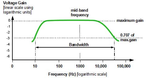
Fig. 1.1.1a Response curve for an audio amplifier
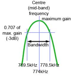
Fig. 1.1.1b Response curve for aRF amplifier tuned to 774kHz
To show how the gain of an amplifier varies with frequency, a graph, showing the frequency response of the amplifier is used. Fig. 1.1.1a shows the typical frequency response curve of an audio amplifier, and Fig. 1.1.1b, that of a RF amplifier. In such graphs, it is common that very large values may be encountered for both gain and frequency. For this reason it is usual for both the frequency and gain axes of the graph to use logarithmic scales. It can be seen from Fig. 1.1.1a that scales on the (horizontal) x-axis do not increase in a linear manner; each equal division represents a tenfold increase in the frequency plotted. This ensures that a very wide range of frequency can be plotted on a single graph. The (vertical) y-axis uses linear divisions but logarithmic units (deciBels dB). The curve of the graph shows how gain, measured in deciBels, varies with frequency.
Comparing Figs. 1.1.1a and b drawn in this manner, shows how each type of amplifier (audio, RF etc) has its own characteristic shape of frequency response curve. An amplifier which has a very narrow, sharply peaked response curve is said to be very "selective". This is typical of an RF amplifier and is precisely what is needed in an amplifier designed for the tuning stages of a radio where only one radio carrier wave among many hundred others, crowded along the medium wave band for example, must be selected.
Bandwidth
An important piece of information that can be obtained from a frequency response curve is the Bandwidth of the amplifier. This refers to the ‘band’ of frequencies for which the amplifier has a useful gain. Outside this useful band the gain of the amplifier is considered to be insufficient compared with the gain at the centre of the bandwidth. Bandwidth specified for voltage amplifiers is the range of frequencies for which the amplifier’s gain is greater than 0.707 of the maximum gain (see Fig. 1.1.1.b). Alternatively, decibels are used to indicate the gain, the ratio of output to input voltage, (see Fig. 1.1.1.a). The useful bandwidth in Fig. 1.1.1a would be described as extending to those frequencies at which the voltage gain is −3dB down compared to the gain at the mid band frequency. Several ways of describing the bandwidth can be used, firstly it could be said (of Fig 1.1.1a), that "The bandwidth is from 10Hz to 20kHz." Alternatively it could be said (of Fig. 1.1.1b) "The bandwidth is 9kHz, centred on 774kHz." or even that it is "774kHz plus or minus 4.5kHz."
Input Impedance
The word impedance means opposition to AC current flow. At 0 Hz, (that is, DC) impedance (symbol Z) is the same as resistance (R), but at frequencies other than 0Hz impedance and resistance are not the same. The input impedance of an amplifier is the effective impedance between the input terminals. "Effective" means that the impedance is not necessarily just that of the amplifier components (resistors, capacitors etc.) actually connected across the input terminals, but is the impedance experienced as the amount of current able to flow into the input terminals for a given signal voltage applied at a particular frequency. Input Impedance is influenced by a number of factors including the frequency of the applied signal, the gain of the amplifier, any signal feedback used and even what is connected to the output of the amplifier.
Output Impedance
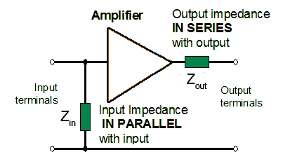
Fig. 1.1.2 Amplifier Input and Output Impedances
The output impedance of an amplifier is not solely dependent on the actual components connected within the output of an amplifier. It is an ‘apparent’ impedance and can best be demonstrated as being responsible for a fall in signal voltage at the output terminals of an amplifier, when a current is drawn from the output terminals. The more current drawn from the output terminals, the greater the reduction in output signal voltage. The effect is that of an impedance or resistance in series with the output terminals.
Calculation of gain in multi stage amplifiers.
Matching of inputs and outputs is necessary to ensure that the maximum amount of signal can be transferred between the amplifier, and any other circuit or device preceding or following it. This is usually the case when the gain of a single amplifier is insufficient for a given purpose. Then several stages of amplification are used which involves feeding the output of one amplifier into the input of another. (This is called connecting the amplifiers in ‘Cascade’). In such designs the output impedance of the first amplifier and the input impedance of the second amplifier form a potential divider, as shown in Fig. 1.1.3
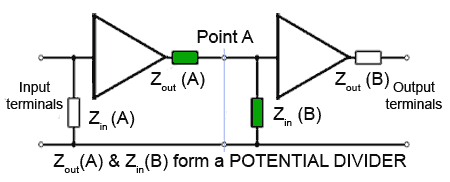
Fig. 1.1.3 Potential divider effect of amplifiers in Cascade
When connecting voltage amplifiers in cascade, the input signal to the second stage should ideally be 100% of the output voltage of stage 1, i.e. have as high a voltage amplitude as possible. This will occur if the output impedance of the first amplifier is a much lower value than the input impedance of the second amplifier. This allows most of the voltage available at the output terminal (point A) to be developed across the input impedance of the second amplifier (and therefore across its input terminals) rather than across the first amplifier´s output impedance.
If the second amplifier is a current amplifier however, it will be necessary that as much current as possible flows into its input terminals. In this case therefore, the input impedance of the second amplifier must be low. In the case of power amplifiers, the maximum power is transferred from output to input if both impedances are equal.
The values of input and output impedance have a considerable effect on the gain of multi stage amplifiers, and there is always some loss of signal amplitude which occurs due to the coupling of successive amplifier stages. In calculating the overall gain of a multi stage amplifier, the overall gain should be equal to the product of the individual gains of each amplifier. i.e. if each stage of a two stage amplifier has a gain of 10, then the overall gain should be 10 x 10 = 100. In practice however, this is not achievable due to the coupling losses incurred in matching the amplifiers, and a slightly lower overall gain results.
Phase Shift
Phase shift in an amplifier is the amount (if any) by which the output signal is delayed or advanced in phase with respect to the input signal expressed in degrees. If a phase shift of 90 degrees occurs then the peak of the output wave occurs one quarter of a cycle after the peak of input wave. Such a shift can be caused by the effect of components such as resistors inductors and capacitors in the amplifier circuit. The action of the transistor in a single stage amplifier can cause 180 degrees of phase shift, and therefore the input and output will be in "anti-phase." Whether a phase shift in an amplifier is important depends on the purpose of the amplifier.
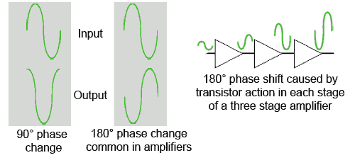
Fig. 1.1.4 Phase Shift
The design of multi stage amplifiers must take phase shift into consideration, as the amount of phase shift will vary with frequency it is possible that at some frequencies the total phase shift may add up to 360 degrees. If the output signal of such a system is allowed to re-enter the input then positive feedback occurs and the amplifier will become unstable and is likely to oscillate.
Feedback
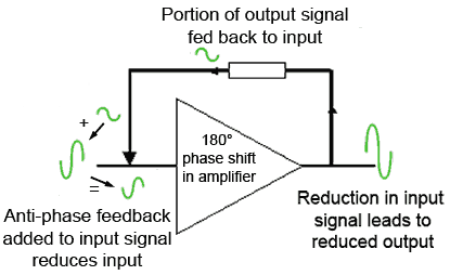
Fig. 1.1.5 Negative feedback reduces gain, distortion and noise, it also increases bandwidth.
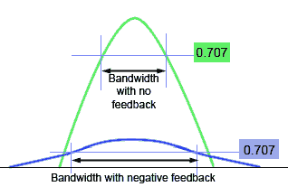
Fig. 1.1.6 How negative feedback affects bandwidth.
Feedback is the process of taking a proportion of an amplifier´s output signal and feeding it back into the input. Feedback can be arranged to either increase or decrease the input signal. When feedback is used to increase the input signal it is called POSITIVE FEEDBACK, and when the effect of the feedback reduces the input signal it is called NEGATIVE FEEDBACK.
POSITIVE FEEDBACK occurs when the feedback signal is in phase with the input signal, this increases the amplitude of the input and hence the output signal, effectively increasing the gain of the amplifier.
NEGATIVE FEEDBACK occurs when the feedback signal is in anti-phase with the input signal, effectively reducing the amplitude of the input and hence also the output signal. This causes a reduction in gain. See Fig. 1.1.5.
In high quality amplifiers negative feedback is often used to reduce the gain of the amplifier. A particular benefit of this, is that any distortion of the signal or background noise produced by the amplifier is also reduced.
A further beneficial effect is that applying negative feedback increases the bandwidth of the amplifier. The reason for this can be seen in Fig. 1.1.6 where reducing the height of the gain curve produces wider spacing of the 0.707 points, therefore widening the bandwidth.


