Module 4.1
Amplifier Input Compensation
- After studying this section, you should be able to:
- Recognise the need for changing the shape of an amplifier’s frequency response.
- Understand the operation of typical circuits for:
- • Input Compensation.
- • Line Level.
- • Phono De-emphasis.

Providing Inputs for Different Signal Sources
Pre amplifiers are designed to increase the signal voltage amplitude of input devices to a level suitable for the input to a power amplifier. Pre-amplifiers often need a number of different inputs, each with a different gain and/or different input impedance. This is to ensure that each device connected to the various inputs provides (after pre-amplification) an output level sufficient to drive the input of a power amplifier and provide full power (when full volume is used) and minimum noise.
Line Level
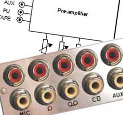
This pre amplifier output is usually called ‘Line level’ and most amplifiers will have a line in and a line out socket, on PC sound cards these are normally coloured pale green and light blue respectively. The actual line level measured in volts varies between different types of equipment but is around 1Vpp on consumer equipment to 2.5Vpp on professional equipment. With some input devices such as CDs or radio tuners, little or no pre-amplification is needed but devices such as microphones, phono inputs and guitar pickups provide much lower signal levels and need specially adapted inputs to the pre-amplifier.

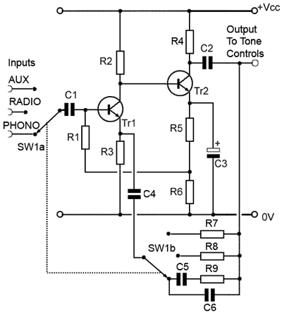
Fig. 4.1.1 Two Stage Pre-amp with Input Compensation
Phono Inputs
Inputs for phono cartridges used for playing legacy vinyl discs have an output of only a few millivolts and so need substantial amplification to reach line level. They also need the frequency response to be modified, due to the ‘pre-emphasis’ applied to these discs during recording.
Fig. 4.1.1 shows a two stage pre-amplifier circuit in which the negative feedback is applied via resistors selected by the input selector switch, allowing different gain levels to be set by choosing one of three resistors (R7, R8 or R9) which will form a potential divider with R3 to set the gain.
R9 (selected in the ‘phono’ position of SW1) also has capacitors connected in series and in parallel with it to form a frequency selective network. The phono input is designed to accept a low level input from a record pick up.
RIAA Pre-emphasis
Vinyl discs recorded to the RIAA (Recording Industry Association of America) standard have the high frequency end of their spectrum excessively amplified during the recording process and the lower frequencies reduced in amplitude. This has two main beneficial effects, firstly amplifying the higher frequencies gives a significant improvement in the signal to noise ratio. Vinyl discs are prone to surface noise in the form of a high frequency hiss; increasing the signal amplitude of the higher frequencies during recording makes the HF signal much louder than the hiss, then reducing the amplitude of the boosted high frequencies (the signal along with the hiss) back to a ‘normal’ level during playback, restores a level frequency response at the same time as reducing the hiss to a much lower level, greatly reducing the apparent surface noise.
A second advantage of reducing the amplitude of the lower frequencies during the recording of vinyl discs, is that it reduces the amount of side-to-side movement required by the groove-cutting stylus and so makes a narrower groove, this allows more information to be recorded on the same diameter disc.

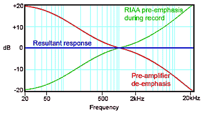
Fig. 4.1.2 RIAA Pre-Emphasis Curve
The result of this pre-emphasis is the standard RIAA curve shown in Fig. 4.1.2. This curve governs the amount of pre-emphasis applied and so requires the amplifier to have a similar but opposite sloping ‘de-emphasis’ curve to produce a flat response.


