
Google Ads
Module 2.0
Resistor Construction
- After studying this section, you should be able to:
- • Describe common types of resistor construction.
- Surface Mount Technology(SMT).
- Carbon Film Resistors.
- Carbon Composition Resistor.
- Wire-wound resistors.
- Metal film resistors.
- Thermal Fuse Resistors
Fixed Resistors
Fig 2.0.1 Resistor Symbols
Resistors are components used to resist the flow of electric current and have a stated value of RESISTANCE. Many types of resistors are used having different uses and construction. The most common types have a fixed value of resistance so are often called fixed resistors. They are shown on circuit schematic diagrams (theoretical diagrams that show how the circuit components are connected electrically, rather than what a circuit looks like physically) using one of the symbols shown in Fig 2.0.1.
Various types of fixed resistors are used in circuits, they are the most numerous of all electronic components and their most common job is to reduce voltages and currents around a circuit so that ‘active components’, transistors and integrated circuits for example, that carry out tasks such as producing or amplifying signals within the circuit are supplied with the correct voltages and currents to work properly.
Resistors are also used in conjunction with other components such as inductors and capacitors to process signals in many ways.
Because resistors are ‘passive components’ they cannot amplify or increase voltages currents or signals, they can only reduce them. Nevertheless they are a most essential part of any electronic circuit.
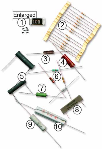
Fig 2.0.2 Fixed Resistor Types
 SMT (Surface Mount Technology)
Many modern circuits use SMT resistors. Their manufacture involves depositing a film of resistive material such as tin oxide on a tiny ceramic chip. The edges of the resistor are then accurately ground, or cut with a laser to give a precise resistance (which depends on the width of the resistor film), across the ends of the device. Tolerances may be as low as ±0.02%. Contacts at each end are soldered directly onto the conductive print on the circuit board, usually by automatic assembly methods. SMT resistors normally have a very low power dissipation. Their main advantage is that very high component density can be achieved.
 Carbon Film Resistors
Similar construction to Metal film resistors but generally with wider tolerance (typically +/- 5%), shown in Fig. 2.0.2 mounted on paper strips for machine insertion into printed circuit boards. Small resistors are extremely inexpensive components and are also often sold in batches of 10s or 100s in this form for easier handling.
 Carbon Composition Resistor
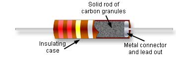
Carbon composition is the oldest design and usually the cheapest of the resistors. Carbon granules are mixed with a filler material and inserted into a tubular casing. In earlier types vulcanised rubber was used but in modern designs the carbon is mixed with a ceramic filler. The value of resistance is determined by the amount of carbon added to the filler mixture. Carbon composition resistors do not have the close tolerances of either carbon or metal film types. Typical tolerances are +/-10% or 20%. One advantage however is that they are better suited to applications involving large voltage pulses than the more modern types.
Google Ads
 1Watt resistor
Carbon composition, carbon and metal film resistors are available in a range of power ratings, from 0.125W to 5W. In a resistor, the power that the resistor must dissipate (get rid of as heat) depends on the voltage difference (V) across the resistor, and the current (I) flowing through it. These are multiplied together to obtain the amount of power (P) that must be dissipated using the formula P = IV. For any particular type or value of resistor, the greater the power rating, the larger the physical size of the resistor.
 Wire-wound resistors
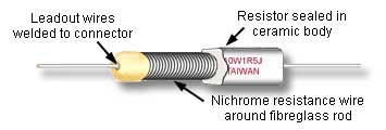
Wirewound resistors are very variable in construction and physical appearance. Their resistive elements are commonly lengths of wire, usually an alloy such as Nichrome (Nickel/Chromium) or Manganin (Copper/Nickel/Manganese) wrapped around a ceramic or glass fibre rod or tube and coated in an insulating flameproof cement film. They are normally available in quite low values of resistance (single ohms to a few Kilohms) but can dissipate large amounts of power. In use they may get very hot.
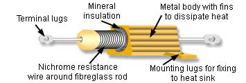
For this reason high power wirewound resistors may be housed in a finned metal case that can be bolted to a metal chassis to dissipate the heat generated as effectively as possible. With all types of wirewound resistor, fire protection is important and flame proof cases or coatings are vital. Lead-out wires are normally welded rather than soldered to the resistor.
 Metal film resistors.
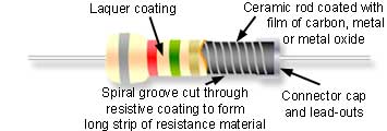
These resistors are made from small rods of ceramic coated with metal such as a nickel alloy or a metal oxide such as tin oxide. The value of resistance is controlled firstly by the thickness of the coating layer; the thicker the layer, the lower the value of resistance. Also by a fine spiral groove cut along the rod using a laser or diamond cutter to cut the carbon or metal coating effectively into a long spiral strip, which forms the resistor. Metal film resistors can be obtained in a wide range of resistance values from a few Ohms to tens of millions of Ohms with a very small TOLERANCE. For example a typical value might be 100KΩ ±1% or less i.e. for a stated value of 100KΩ the actual value will be between 99KΩ and 101KΩ. Note that although the body colour (the colour of the laquer coating) on metal film resistors is often grey, this is not a reliable guide. Small carbon, metal and oxide resistors may be made in various body colours such as dark red, brown, blue, green, grey, cream or white.
 5 Watt Wirewound Resistor
A wirewound resistor can have a smaller physical size for a given power rating than carbon composition or film resistors, compare this 5W resistor with the 1W resistor (labelled 3 in Fig.2.0.2). Wirewound resistors however, do not not have the close tolerance of composition or film types. This 4R7 resistor has a tolerance of ±10%.
 PCB Mounting Wirewound Resistor
Wirewound resistors usually have a resistance range from around 1Ω to about 50KΩ. Because they use a coil of wire as their resistive element they tend to act as inductors to some degree. This limits their use to low frequency circuits up to around a few tens of kiloHertz (kHz). This example, available in power ratings up to 25W, is for mounting on a printed circuit board and to prevent heat damage to the board, the specially shaped legs ensure an air gap between the resistor and the board. The whole resistor is enclosed in a flameproof ceramic layer.
 High Power Metal Film
Metal film resistors are also available in high power types with power ratings less than wirewound types (typically less than 5W) but having closer tolerances.
 Fusible Wirewound Resistor
In this fusible resistor, the current flowing through the resistor first flows through a spring loaded connection that is positioned close to the body of the resistor. The heat generated by the wirewound resistor under normal conditions would not be sufficient to melt the blob of solder holding a spring wire in place. If too much current flows through the resistor it overheats, the solder melts and the wire springs up, opening the connection and stopping the current. This then requires a service technician to find the cause of the over-current before re-soldering the spring connection to restore normal operation. It is important to use the correct type of solder (usually stated in the service manual for the equipment) when re-soldering, since this will affect the temperature at which the spring opens.
Google Ads