Module 3.4
Negative Feedback & Distortion
- After studying this section, you should be able to:
- Understand the causes of distortion in common emitter amplifiers.
- • Amplitude distortion.
- • Frequency distortion.
- • Phase distortion.
- Understand methods of reducing distortion.
- • Biasing.
- • Negative feedback.
- • DC coupling.
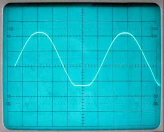
Distorted Sine Wave
Causes of Distortion
In any amplifier the output waveform is a less than perfect reproduction of the input waveform, because the process of amplification introduces some distortion. The changes introduced can be due to one or more of the following effects.
a.) Amplitude Distortion.
b.) Frequency Distortion.
c.) Phase Distortion.
Amplitude Distortion
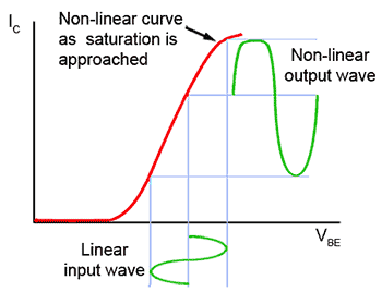
Fig. 3.4.1 Amplitude Distortion caused
by poor DC biasing.
Amplitude distortion, also called Non-Linear distortion, is caused by the effect of the non-linear characteristics of transistors reducing the amplification applied to the positive and negative tips of the waveform as shown in Fig. 3.4.1. Although the sections of the wave either side of the waveform’s centre are unaffected, the overall amplitude of the waveform is reduced. The reduction in amplitude in audio signals is however, much less noticeable to the ear than the associated change in shape of the waveform tips.
When the peaks of a sine wave become flattened, due to the non linearity of the amplifier’s characteristics, as shown in Fig. 3.4.1, odd harmonics of the original (fundamental) wave are created. Fig. 3.4.2 shows what happens when odd harmonics (the 3rd to 15th) are added to the fundamental; the result is a squaring effect of the wave.
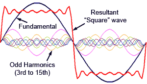
Fig. 3.4.2 Adding odd harmonics
to a sine wave.
In a practical situation, when the tips of a sine wave become flattened, and the wave consequently becomes more square, many more odd number harmonics will be added, as shown in Fig.3.4.2. Each of these extra sine waves, caused by the flattening of the waveform peaks, will have a frequency that is an odd multiple of the fundamental, and these frequencies will in turn, add and subtract from other frequencies present in the wave shape to produce many more waves at yet more frequencies. Some of these new frequencies will be outside the bandwidth of the amplifier, but some will be within the bandwidth and be audible. The result of this ‘odd harmonic distortion’ on the ear will be a note having a harsher sound than the original.
To hear the difference that changing the waveshape can make, play this audio clip containing 5 seconds of pure 440Hz sine wave followed by 5 seconds of 440Hz Square wave.
Correct biasing prevents one peak of the waveform distorting before the other, as shown in Fig. 3.4.1 where the positive going peak of the input wave is driving the transistor into saturation and causing the collector current waveform to be ‘clipped’.
Using negative feedback to control the gain of the amplifier stages can also reduce amplitude distortion by ensuring that a signal level is not reached where the output waveform of one stage may drive a following stage into its saturation and/or cut off regions.
Frequency Distortion
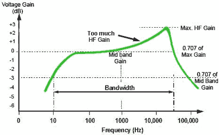
Fig. 3.4.3 Too much HF gain.
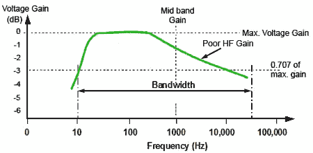
Fig. 3.4.4 Insufficient HF gain.
Frequency distortion describes the condition where different frequencies within the amplifier’s bandwidth are amplified by different amounts. The gain over the bandwidth is no longer flat. Under these conditions the various frequency components of complex waves are amplified by different amounts and the wave becomes distorted.
Frequency distortion can be caused by the frequency dependent effects of reactive components (capacitances and inductances) in the circuit. Figs. 3.4.3 and 3.4.4 illustrate the effects of frequency distortion on the response curve of an amplifier.
Testing for Frequency Distortion
Frequency distortion can be detected when present, by using a square wave as the amplifier input signal and monitoring the output waveforms. Fig. 3.4.5 shows how frequency distortion can affect the transient response of a square wave (waveform a.).
Waveform b.) shows the effect poor (insufficient) LF gain on the reproduction of a square wave. The amplifier is unable to respond to the fast rising and falling edges of the input wave, the delaying effect this causes is also likely to produce unwanted phase changes.
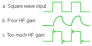
Fig. 3.4.5 Frequency distortion
Waveform c.) shows the effect of excessive HF response amplifying the higher harmonics preset in a square wave to such a degree that the fast transients (the rising and falling edges of the wave) are overshooting and even beginning to oscillate, causing a ‘ringing’ effect on the waveform.
Negative feedback has an important role in helping prevent frequency distortion. As the worked example in Module 3.1 illustrates, applying NFB keeps the closed loop gain at a constant level for even large changes in open loop gain. This effect of NFB helps produce a flat response curve.
Phase Distortion
A signal passing through the various stages of an amplifier usually comprises of a complex wave made up of many different frequencies and amplitudes. The electrical components of the amplifier circuit may well contain some reactive components such as capacitors and/or inductors as well as resistors; where these combinations of components exist they may form LC, LR, CR and/or LCR filter networks and change the amplitudes of individual waves at different frequencies.
A further property of filters is that they also change the phase of waves at different frequencies. An individual frequency component of the complex wave having it’s phase is shifted by 180° would convert a negative feedback amplifier into a positive feedback amplifier at particular frequencies and cause severe instability. Even if the phase change effect is less than this, shifting the phase of some of the component waves or harmonics of the complex signal can have the effect of changing the shape of the signal wave and so cause distortion.
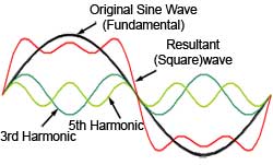
Fig. 3.4.6 The Effect of Adding
In-phase Odd Harmonics
Figs. 3.4.6 and 3.4.7 show what can happen when the phase relationship between the fundamental sine wave component of a complex wave (shown in black) and its harmonics is changed. Fig. 3.4.6 shows a sine wave (the fundamental) together with its 3rd and 5th harmonics. Adding these harmonics to the fundamental produces a resultant wave (shown in red) that is beginning to look like a square wave, in fact adding an infinite number of odd harmonics in this way would produce a perfect square wave. Notice also that in this case the harmonics all have the same phase, i.e. they all start by going positive at the same time as the fundamental, and end the cycle by returning to zero at the same time as the fundamental.
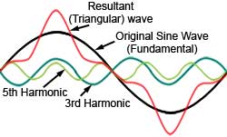
Fig. 3.4.7 The Effect on Fig.3.4.6
of inverting the 3rd Harmonic
Fig. 3.4.7 shows the same fundamental wave, again with the same two odd harmonics, but this time the third harmonic has its phase shifted by 180 degrees; now the resultant complex wave looks more like a triangular wave.
Although this is an extreme case of phase distortion, it demonstrates that phase shifts in only a few harmonics (i.e. phase changes taking place at just a few critical frequencies) can significantly change the shape of signal waves.
Phase distortion in audio signals is less noticeable to the human ear than amplitude or frequency distortion, but it is critical to avoid phase distortion in video signals, where the distortion becomes visible. Phase distortion can be limited by avoiding the use of reactive components such as capacitors and inductors in both the amplifier and any feedback loops where possible. For this reason direct (DC) inter-stage coupling is the preferred method in many amplifiers.


