Module 2.4
Colpitts Oscillator Practical Project
- After Studying this section, you should be able to:
- • Build a Colpitts Oscillator from given instructions.
- • Test the Colpitts Oscillator for correct operation.
- • Take measurements on a Colpitts Oscillator.
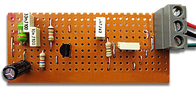
Fig. 2.4.1 Colpitts Oscillator
Build a Colpitts Oscillator
Build the Colpitts oscillator shown using either breadboard (proto board) or strip board, then test the oscillator’s operation using a multi meter and oscilloscope.
Building and testing your own circuit is a really effective way to learn about oscillators!
The Oscillator Circuit
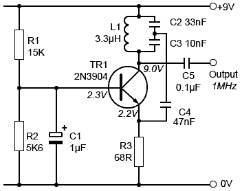
Fig. 2.4.2 Colpitts Circuit
This Colpitts oscillator produces a sine wave output in excess of 12Vpp at an approximate frequency set by the values chosen for L1, C2 and C3. It will operate from a 9V battery, or a DC power supply up to 12V. Supply current at 9V is around 20mA. The circuit can be built on breadboard for testing purposes, where it will be found that the value of R3 is fairly critical. This 68 ohm resistor could be replaced by a slightly higher or lower value to alter the amplifier gain for experimentation. The values given for the circuit should work reliably when built on strip-board.
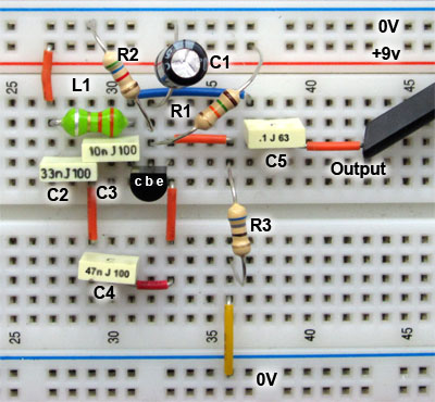
Fig. 2.4.3 Colpitts Oscillator - Breadboard Version
Components List
- TR1 = 2N3904
- C1 = 1µF
- C2 = 33nF
- C3 = 10nF
- C4 = 47nF
- C5 = 100nF
- R1 = 15KΩ
- R2 = 5.6KΩ
- R3 = 22Ω (or 470Ω variable)
- L1 = 3.3µH
Construction on Breadboard (Protoboard)
Construct the circuit on breadboard and experiment with different component values. The values shown on the circuit schematic above should give reliable oscillation. Note how some values produce different amplitudes or better wave shapes. It should be possible to obtain a good sine wave with a peak to peak output amplitude even greater than the supply voltage. This is a particular feature of LC oscillators as the AC output voltage depends on the amount of current circulating around the tuned circuit at resonance. But remember that a larger output voltage will also mean a higher collector current.
Colpitts Oscillator Construction on Stripboard
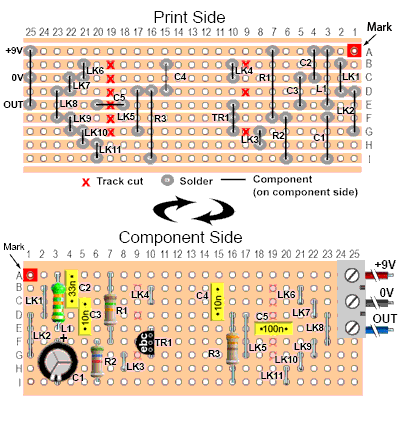
Fig. 2.4.2 Colpitts Oscillator - Stripboard Version
Additional Components For Stripboard Version
- Strip board 9x25 holes
- 3 way connection block (Optional)
- 9V battery connector (Optional)
- Tinned copper wire (for links)
- Insulated flexible wire(for external connections)
Construction - Stripboard Version
- On a piece of 9 x 25 hole strip-board, mark hole A1 to ensure that counting the strips and holes for placing track cuts and components always starts from the same point.
- Mark the holes where track cuts are to be made. Double check their correct position before cutting.
- Make the track cuts.
- Solder the wire links in place.
- Solder the components in place in the following order.
- Resistors.
- Inductor.
- Polyester capacitors.
- Transistor (check for correct e b c positions before soldering).
- Electrolytic (check for correct polarity before soldering).
- Terminal Block.
Double check for correct positions and values of components
Carefully check for any short circuits made by solder bridging adjacent tracks, and for any poorly soldered joints.
Connect up the power supply and connect an oscilloscope to the output.
Colpitts Oscillator Measurements
Having built the Colpitts oscillator, either on breadboard or strip board, check that the circuit is oscillating satisfactorily, then complete the measurements in Tables 1 and 2.
| Table 1 | |
|---|---|
| Take the following measurements with the circuit oscillating in class C: | |
| The supply current | |
| The supply voltage | |
| TR1 collector voltage | |
| TR1 base voltage | |
| TR1 emitter voltage | |
| Table 2 | |
|---|---|
| Temporarily stop the oscillations by connecting a 0.47μF (non-polarised) capacitor across either L1 and take the following measurements: | |
| The supply current | |
| TR1 collector voltage | |
| TR1 base voltage | |
| TR1 emitter voltage | |
| Table 3 | |
|---|---|
| The Peak to Peak Voltage | |
| DC Level of the Wave | |
| Periodic Time (T) of the Wave | |
| Frequency of the wave (1/T) | |
| Frequency of the wave calculated by ƒ= 1/ 2π√(LC) | |
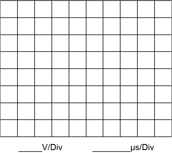
Connect an oscilloscope to TR1 collector and adjust the CRO display to show one to two cycles of the collector waveform. Draw the waveform on the grid.
Enter the time/division and volts/division settings of the CRO in the spaces provided.
Calculate the values in Table 3 from the waveform:
