Module 4.0
CR Relaxation (Square Wave) Oscillators
- Section 4.0 Introduction.
- • Relaxation oscillators.
- • Properties of square waves.
- Section 4.1 BJT Astable Multivibrators.
- • How BJT astables work.
- Section 4.2 Op-amp Astables.
- • Op-amp Astable operation.
- • Modifications to the basic op-amp astable.
- Section 4.3 555 Astables.
- • The 555 timer IC.
- • The 555 Astable Operation.
- Section 4.4 555 Astable Design.
- • Designing 555 Astables.
- • Duty cycle control.
- Section 4.5 555 as a Monstable.
- • Monstable operation.
- • Timing for monostables.
- Section 4.6 Pulse Width Modulation.
- • Astables & monostables for PWM.
- • Simple motor speed control.
- Section 4.7 Square Wave Oscillator Quiz.
- • Check your knowledge & understanding.
Introduction
There are a number of oscillator designs that produce square waves at frequencies from less than 1Hz to several GHz. Square waves are used to control the timing of operations in digital systems, such as clock generators for microprocessors. They also have many uses in analogue circuits from simple lamp flashers to complex control systems as well as pulse width control systems for audio and radio applications.
These different circuits go under a variety of names, such as:
Astable oscillators
This name comes from the fact that these oscillators have no stable state; their output changes repeatedly from high to low and back to high.
Astable multivibrators
Some astables consist of more than one (e.g. two oscillating amplifiers).
Aperiodic Oscillators
Because they are untuned oscillators.
Clock Oscillators
In digital applications the main function of these oscillators is the production of square wave outputs, or pulse trains.
Square wave oscillators can also be used as the basis for sawtooth oscillators or sweep generators.
Properties of Square Waves
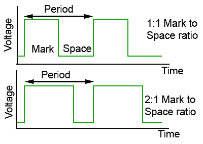
Fig. 4.0.1 Mark to Space Ratio
Square waves may be perfectly symmetrical with the height and width of both the mark and the space being equal, but this is not necessarily the case. Where the mark and the space are of equal width (time), the waveform is said to have a mark to space ratio of 1:1 but in the lower waveform in Fig. 1 the mark is twice the width of the space and so the mark to space ratio is 2:1.
The height (Voltage) of the mark does not need to be equivalent to its width, provided that the voltage and timing of the waveform is known.
Waveforms of a rectangular rather than square shape can also be considered square waves.
Where the time of the mark is much shorter than that of the space however, the waveform is more properly called a series of pulses or a pulse train as shown in Fig. 4.0.2.
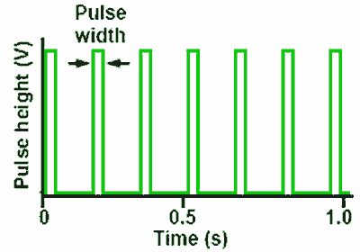
Fig. 4.0.2 Pulse Train
With pulses the frequency of the wave is more usually referred to as the “Pulse repetition frequency” (p.r.f.), which refers to the number of pulses occurring in one second rather than the more usual Hz or cycles per second.
A square wave is a complex wave, meaning that unlike the sine wave, which has only a single sine component, it is made up of many sine wave components. It has a ‘fundamental’, a sine wave of the same amplitude and frequency as the square wave, plus, in a perfect square wave, an infinite number of odd harmonics. This means that to produce a perfect square wave, the oscillator and any circuits being fed by it, must have an infinitely wide bandwidth, with constant gain over the whole bandwidth. As this level of perfection is not practicable, it is to be expected that some distortion of the square wave will be present. Figs 4.0.3, 4 and 5 illustrate some commonly encountered distortions to square waves.
Rise and Fall Time
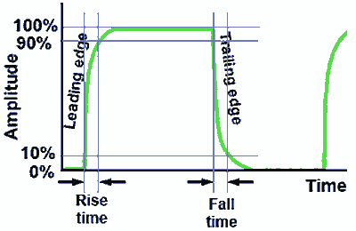
Fig. 4.0.3 Slow Rise & Fall Times
Fig. 4.0.3 shows a square wave in which the vertical edges are not vertical. The rise and fall in voltage should be instantaneous but here there is a distinct lengthening of the rise and fall times plus a certain amount of rounding of the waveform. This is typical of poor high frequency response in an oscillator or amplifier circuit, the higher frequency harmonics are reduced or missing, also causing a ‘rounding’ of the waveform. A similar effect, but without the rounding can be evident at higher frequencies in op amp astables due to slew rate limiting.
Ringing
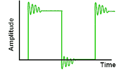
Fig. 4.0.4 Ringing
Fig. 4.0.4 Illustrates ‘Ringing’ following the vertical transitions of the wave, this may be caused by the presence of stray inductance and capacitance in the circuit causing damped oscillations to begin at some high frequency, together with large high frequency gain.
Overshoot
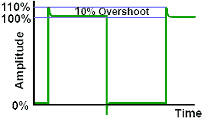
Fig. 4.0.5 Overshoot
Fig. 4.0.5 illustrates ‘Overshoot’ where the rising and falling edges of the wave continue above and below the maximum amplitude of the wave. Overshoot is generally measured as a percentage of the total (normal) amplitude of the wave. It may be caused by the presence of stray inductance creating excessive high frequency gain.


