Module 4.4
Designing 555 Astables
- After Studying this section, you should be able to:
- • Calculate values of R and C to give an astable of a required frequency.
- • Understand methods for varying the duty cycle.
- • Understand methods for reducing the effects of noise.
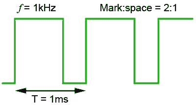
Fig. 4.4.1 Design a 555 Astable to Produce This Wave
Designing 555 Astable Oscillators
If an oscillator of a particular frequency and mark to space ratio is required, (see Fig. 4.4.1) the method would be to calculate periodic time from the required frequency and the discharge time and charge time using the formulae for tD and tC described in Oscillators Module 4.3. To do this, some component details will be needed.
Starting with C1, a suitable value can be assumed from the diagram in Fig. 4.4.2, which shows that for an astable having a frequency of 1kHz, and so for a periodic time of 1ms, capacitors of 1nF to 1μF would suffice, depending on which of the total resistances (indicated by the red lines) was chosen.
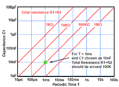
Fig. 4.4.2 Finding Suitable Values for C1
Manufacturers specify the maximum total resistance that may be used with their particular variant of the 555, and these maximum values are usually around 10 to 20MΩ, however using such high values can increase the error between calculated and actual frequencies, so for many uses a 1MΩ maximum can be recommended. The minimum total resistance value for the combination of R1 and R2 depends largely on the value of R1. The junction of R1/R2 is connected to pin 6 and to the trigger input pin 2. If the value of R1 is less than about 1KΩ, there is a danger that the trigger input may not be able reach a low enough voltage to trigger comparator 1, and so oscillations cannot take place.
From this it can be assumed that if R1 must be 1KΩ or above and R1 + R2 should be kept below 1MΩ; a 10nF capacitor would allow a suitable total resistance of around 100KΩ to be calculated.
Example
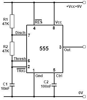
Fig. 4.4.3 555 Circuit for 1kHz
2:1 Mark to Space Ratio
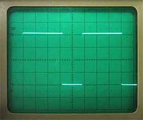
Fig. 4.4.4 Output 1kHz
2:1 Mark to Space Ratio
To design a 555 astable with a frequency of 1kHz and a mark to space ratio of 2:1
Periodic time T = 1/f = 1/1000 = 1ms
Charge time tC = 2/3T = 667μs
Discharge time tD = 1/3T = 333μs
Assuming (from Fig. 4.4.1) a 10nF capacitor will be used, which discharges via R2 only:
tD = 0.7 x R2 x C1
Re-arranging the formula to find R2 gives:

During the charge time C1 charges via R1 + R2, therefore:
tC = 0.7 x (R1+R2)x C1
Rearranging the formula to find (R1+R2) gives:

As R1 = (R1+R2) - R2 then:
R1= 95.3KΩ – 47.6KΩ = 47.7KΩ
Choosing the nearest preferred values for R1 and R2 gives the value 47KΩ for both resistors.
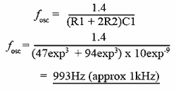
To check that two 47KΩ will give the required frequency of 1kHz, simply apply the frequency formula for a 555 astable using the calculated values:
Mark to Space Ratio
The basic 555 astable design described above uses two timing resistors when producing square waves. In timing the high (charging) period the timing capacitor (C1 in Fig. 4.4.3) is charged via R1 and R2, but only R2 is used whilst discharging C1.
In this basic configuration, the resistance used for timing the high period must always be greater than that used during the low period. The high period of the wave must therefore always be longer than the low period. It follows that the basic version of the 555 astable produces square waves than can be nearly, but never quite 1:1 mark space ratio square waves.
Duty Cycle
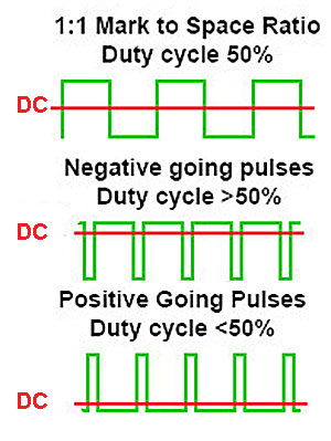
Fig. 4.4.5 The Effect of Duty Cycle on DC Level
The mark to space ratio of a square wave or pulse oscillator is often referred to as the Duty Cycle. This is a more useful term when the purpose of an output wave is to drive some device such as a motor. It gives a more useful comparison to the power supplied to the motor than describing the mark to space ratio of the output. Changing the duty cycle changes the average DC voltage or DC current level of the output, as shown in Fig. 4.4.5 and hence the power supplied to control the speed of the motor. This is also important in driving output devices such as lamps, heaters and many others.
The Duty Cycle is a term that describes the percentage of each cycle taken up by the active or high period. For example a square wave with a mark to space ratio of 1:1 has a duty cycle of 50% so the high period takes up 50% of the total period. In the waveform illustrating negative going pulses in Fig. 4.4.5 the duty cycle may be about 80% while in the positive going pulse waveform, the duty cycle may be around 20%.
50% Duty Cycle Astable
Although the basic form of the 555 astable is limited to producing an output with a duty cycle that is always greater than 50%, one of the great benefits of using the 555 timer as an astable oscillator is the ease with which the circuit can be modified to produce a much wider range of duty cycle.
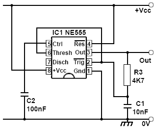
Fig. 4.4.6 One to One Mark to Space Ratio Astable
Where a completely symmetrical output wave (50% duty cycle) is required, an alternative method is to use the circuit shown in Fig. 4.4.6. In this configuration, shown using the pin-out of the actual 555 IC, the timing capacitor is still connected to pins 2 and 6 as in the basic astable circuit, but a single timing resistor is now connected to the output, pin 3.
Operation
During the high period of the waveform C1 charges from the high output via R1 until the voltage at pin 6 reaches 2/3Vcc and triggers comparator 1. The output now goes low and C1 discharges via R1 until the voltage at pin 2 falls to 1/3Vcc when comparator 2 triggers and starts a new charging period. As only one resistor is used for charge and discharge in Fig. 4.4.6 both charge and discharge times are now identical at 0.7CR, which gives a simplified formula for the approximate frequency of oscillation.

There are however, some drawbacks to this solution for obtaining a 50% duty cycle. Surprisingly the circuit may not always produce a 50% duty cycle. One reason for this is that the design assumes that the output of the 555 changes between 0V and Vcc, but in practice the actual output voltage depends to some extent on the load placed on the output. It is common for example, that in a 555 with a 9V supply the output may change between 0V and just a little over 8V, and with different load resistances, this difference between Vcc and output voltage may again vary.
The trigger points at which the 555 IC switches its output are a fixed proportion of Vcc because they are supplied from the three internal resistors between +Vcc and 0V, but the rate at which the timing capacitor in this design charges now depends, not on Vcc as in the basic design, but on the output voltage. Therefore differences in timing can occur because the voltages at the output pin 3 and at Vcc are not the same, this can affect both the frequency and mark to space ratio. However performance can be improved in a number of ways to make a number of useful circuits.
The 555 Control Input
Pin 5 of the 555 is the Control (Ctrl) pin, which in many applications serves only to decouple the inverting input of comparator 1 inside the IC to prevent noise causing incorrect triggering of the circuit. However, this pin can also function as a useful input, allowing the control of the frequency and duty cycle when the 555 is used in astable mode.
The control input is also connected to the resistor chain in the IC that controls the 2/3 and 1/3Vcc trigger points of the circuit. Therefore by externally applying a DC voltage to pin 5, the internally set trigger points can be altered to lengthen or shorten the charge and discharge periods of the generated wave. Measuring the voltage on pin 5 would normally show a voltage of 2/3Vcc, and applying a higher voltage than this would increase the time of the charge period as the timing capacitor has to now reach this higher voltage before comparator 1 triggers. Therefore the higher the voltage on pin 5 the longer the charge period and the lower the frequency of the wave. Reducing the voltage on pin 5 below its normal 2/3Vcc will cause the charge period to shorten and the frequency to increase.
Pin 5 therefore provides a method of changing the frequency of oscillation by applying a DC voltage, and since pin 5 can still be effectively decoupled by quite a large value of decoupling capacitor, the potentiometer for controlling the frequency can be located some distance from the oscillator without the problem of introducing noise to the circuit.
Varying the Duty Cycle
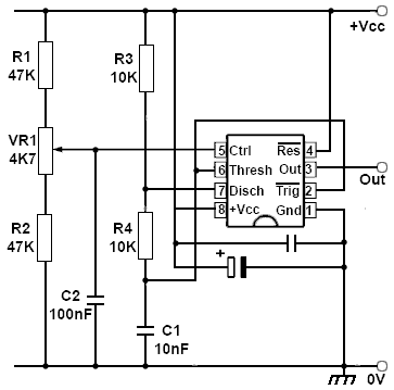
Fig. 4.4.7 Duty Cycle Control Using Ctrl (pin 5)
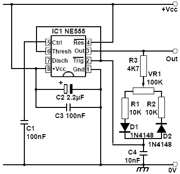
Fig. 4.4.8 Improved Duty Cycle Control
Fig. 4.4.7 shows how simple control over the duty cycle can be implemented in the basic 555 astable circuit by the use of the control input. A potentiometer VR1 is used to apply a variable voltage to pin 5. The limits of variation is set by R1 and R2 so that the control voltage is not allowed to swing to +Vcc or to 0V, allowing the duty cycle to be adjusted over a range above and below 50%. One problem with using the control pin in this way is that it affects both the duty cycle and the frequency at the same time.
Improved Duty Cycle Control
A circuit providing an adjustable duty cycle with a minimal effect on frequency is shown in Fig 4.4.8. This is a modified version of the 50% duty cycle circuit shown in Fig. 4.4.6.
VR1, a linear potentiometer, provides a continually adjustable duty cycle between approximately 35% and 75% avoiding use of the control input therefore allowing adjustment of the duty cycle with little or no effect on the frequency of oscillation.
The two sections of VR1, either side of the slider, added to R1 and R2 effectively provide two separate (and adjustable) values of timing resistor. D1 conducts during the charge period of C4 when the output on pin 3 is high, providing a timing resistance made up of R3, the left hand portion of VR1, and R1. During the discharge period pin 3 is low, so D1 is reverse biased; D2 now provides a discharge path via R2, the right hand portion of VR1, and R3.
The frequency is calculated using the same formula as for the 50% duty cycle circuit shown in Fig. 4.4.6, although this will be slightly affected by the forward resistance of the diodes:
Also, in this circuit R is now made up of R3 + half of VR1 + R2 (or R1, which is the same value). Frequencies from a fraction of 1Hz to many tens of kHz can be obtained from Fig 4.4.8 by using different combinations of values for the timing capacitor C4 and the timing resistors R1, R2 and R3. To obtain a 1:1 mark space ratio with VR1 at its central position, R1 and R2 should be kept equal in value.
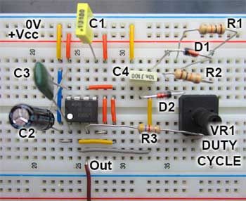
Fig 4.4.9 shows the circuit in Fig. 4.4.8 constructed on Breadboard.
