Module 3.4
Push-Pull Switched Mode Power Supplies
- After studying this section, you should be able to:
- Understand the operation of a push pull DC to DC converter.
- Understand the operation of a typical switch mode controller I.C.
- • Power switching transistors.
- • Pulse width modulator.
- • Over current & over voltage protection.
- • Current sensing.
- Recognise components and methods used for output isolation.
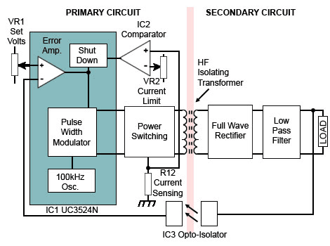
Fig. 3.4.1 Push Pull SMPS Block Diagram
The Push Pull SMPS
Fig. 3.4.1 shows a block diagram of a switched mode power supply designed around a UC3524 Advanced Regulating Pulse Width Modulator by Texas Instruments.
The circuit is a DC to DC converter using a DC input voltage of 15V to 30V and produces a regulated 5V output at a current up to about 250mA. The circuit uses push pull power switching driving a high frequency transformer, which fully isolates the output circuit from the input. The output is short circuit protected, and the output voltage can be manually adjusted. Maximum current can be also manually set using adjustable current limiting.
Primary Circuit.
A 100kHz oscillator within IC1 (UC3524) generates pulses, which are processed by the pulse width modulator (within IC1)used to drive the power switching transistors. The width of the processed drive pulses controls the length of time for which the power switching transistors conduct, and therefore the amount of power delivered to the transformer.
The pulse width and therefore the output voltage is controlled by the error amplifier in IC1. This measures the difference between a sample of the output voltage, fedback via the opto-isolator, and a reference voltage set by Vr1. When these two voltages are equal, the circuit output voltage is correct. If there is a difference, the width of the pulses produced by the pulse width modulator is increased or decreased to correct the error.
Over current protection is provided to ensure that the supply is shut down in the event of too high a current demand at the output. The output terminals can even be shorted together without damaging the supply.
Each pulse of current in the power switching transistors produces a voltage pulse across the sensing resistor R12. The amplitude of these pulses is proportional to the current being delivered to the transformer by the switching circuit. If the peak value of any of these pulses exceeds the DC voltage set by Vr2 (Current limit) then the output from IC2 will cause pulse width modulator input to reduce the width of the pulse being produced by the modulator at that time, momentarily reducing the output voltage. If the over current condition disappears, the output voltage will be restored to its normal level, but if the load current remains high, the current limiter will continue to reduce the pulse width, dependent on the amount of over current, even down to zero in the case of a short circuit output.
The Secondary Circuit
The push pull switching transistors create an AC waveform across the transformer primary winding, and the secondary winding feeds a conventional full wave rectifier and LC low pass filter to supply the load with a stable 5V at the output terminals. Negative feedback to the voltage regulating circuit in IC1 is via the opto-isolator (IC3). The higher the output voltage, the brighter the glow from an LED sealed within the secondary side, and the larger the DC output voltage derived from pin 4 of IC3 in the primary side of the device. This voltage is used as a sample at the inverting input of the error amplifier in IC1 where it is compared with a voltage from the ‘set voltage’ control VR1, to control the pulse width modulator.
Circuit Description
The full schematic diagram for the circuit is shown in Fig. 3.4.2.
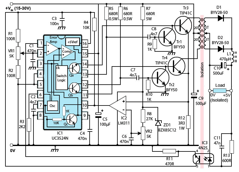
Fig. 3.4.2 Circuit diagram of a push-pull SMPS using the Texas Instruments UC3524 I.C.
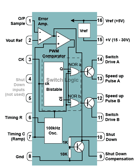
Fig. 3.4.3 The UC3524N (part detail)
The oscillator within IC1 produces narrow 100kHz (approx) pulses that are used as clock pulses for the Switch Logic within IC1. The timing components for the oscillator are R3 and C2. The ramp waveform produced as C2 charges is also used as an input to the inverting input of the comparator in IC1.
The pulse width modulator comprises the comparator within IC1 and the switching logic, which consists of a bistable and two three input NOR gates. The outputs of this block supply variable width pulses to the two transistors Qa and Qb.
The error amplifier compares a stable reference voltage on pin 1 (set by Vr1 supplied from an internally regulated 5V from pin 16) with a sample of the load voltage developed across the opto-isolator emitter resistor, R11. The resulting error voltage is used as the non-inverting input to the PWM comparator.
The facilities of the UC3524 that are used in this circuit are shown in more detail in Fig. 3.4.3 (Note: Some unused facilities of the UC3524 have been omitted for clarity, for more information see the Texas Instruments UC3524 data sheet).
Pulse Width Modulator
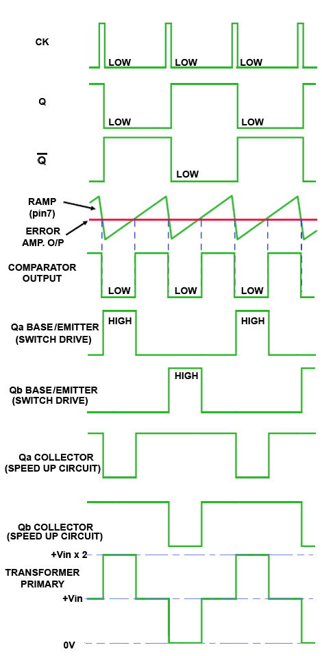
Fig. 3.4.4 UC3524N and Transformer Primary Waveforms
The action of the pulse width modulator, described by the waveforms shown in Fig. 3.4 4 is as follows:
Clock pulses (CK) from the oscillator are fed to the Bi-stable (flip-flop), which produces a square wave with a 1:1 mark/space ratio and a frequency of 50kHz, (half that of the oscillator) at its Q output, and an inverted version of this wave at its Q output.
Output Q provides an input to NOR gate a, and output Q (the opposite of Q) provides an input to NOR gates b. The logic rule for a NOR gate is that its output will be high, only when all its three inputs are low. Notice that the Q and Q signals go low at the start of alternate clock pulse low states. The clock signal also provides an input to both NOR gates.
The third input to each of the NOR gates is provided by the comparator output, which is a series of variable width low state pulses, produced by comparing the DC error voltage from the error amplifier in IC1 with the ramp produced by the oscillator timing capacitor C2.
As each NOR gate output goes high, only when all of its three input signals are low, alternate high state pulses, whose width depends on the value of the error voltage, are fed to the bases of the internal transistors Qa and Qb. The lower the value of the error voltage (due to a higher value of "sample" voltage at pin 1) the narrower the pulses produced. These narrower pulses, when used to turn on the power switching transistors TR3 and Tr4, will lead to a reduction in power in the transformer and a reduction in load voltage.
Power Switching Circuits
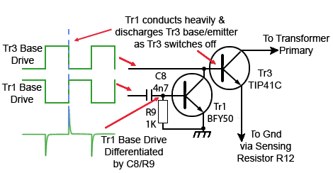
Fig. 3.4.5 Speeding up the Power Switch Turn Off
The internal drive transistors Qa and Qb each produces a series of pulses at its collector, and an a series of anti-phase pulses at its emitter. The emitter signals a and b drive the power switching transistors Tr3 and Tr4 respectively, and the collector signals drive the speed up circuits Tr1/Tr2.
The reason for including the speed up circuits is to overcome the delay that would normally happen because while the power switching transistors Tr3 andTr4 are conducting, their base/emitter junction (which naturally forms a small capacitor due to the depletion layer between the base and emitter layers in the transistor) is charged up, and must be discharged before the transistor will fully turn off.
The power transistor junctions are rapidly discharged by momentarily turning on Tr1 or Tr2 using a differentiated pulse generated from the rising edge of the waveform from the collector of Qa or Qb in IC1, which of course happens at exactly the same instant as Tr3 or Tr4 is turning off, as illustrated in Fig 3.4.5.
Because the transformer primary centre tap is connected to the main (+VIN) supply, it will always be at the supply potential. The collector voltages of Tr3 and Tr4 will also be at +VIN during the periods when both transistors are turned off.
During the ‘on’ pulse of Tr3, its collector will be at approximately 0V, and due to the centre tapping of the transformer primary winding the bottom half of the primary will be in anti-phase to the top half, so the collector of Tr4 will be positive at twice the value of +VIN for the period of the Tr3 ‘on’ pulse. This situation is reversed during the ‘on’ pulse of Tr4. This action produces a stepped type of waveform with an amplitude of +VIN x 2 across the transformer primary as shown in Fig 3.4.4.
The Secondary Circuit
The resulting secondary voltage is rectified by D1 and D2, and smoothed by the low pass filter L1/C10 before being supplied to the load. A sample of the load voltage is fed back to the LED within opto-isolator IC3 via the LED current limiting resistor R13.
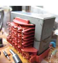
Fig. 3.4.6 Typical High Frequency
Multi-Secondary Transformer
Because of the push pull design used by this circuit, it is a simple matter to arrange for such a circuit to have multiple outputs. Different (higher or lower) voltages can be obtained by using a transformer similar to the one illustrated in Fig. 3.4.6, which has multiple secondary windings with appropriate turns ratios.
The total current supplied to the multiple outputs however, must not exceed the maximum current rating of the SMPS. Each supply line will have its own rectifier and filter system, and may also include some extra point of load regulation. A voltage sample will normally be taken from only one of the outputs to provide feedback to the pulse width modulator however, as controlling the power applied to the transformer primary will control all the voltage outputs.
Current limiting
Current limiting, which is capable of completely shutting down the circuit under extreme overload conditions is provided by the action of IC2 and the shut down transistor between pins 9 and 10 within IC1.
Pin 3 of IC2 is provided with a stable reference voltage derived from the shunt voltage regulator R7/ZD1 via the current limit control Vr2. The non-inverting input of IC2 is connected to a low resistance current sensing resistor R12 in the emitter lead common to both switching transistors Tr3/Tr4.
Every time either transistor conducts, the resulting large emitter current produces a voltage pulse across R12. The peak voltage of this pulse will be proportional to the emitter current flowing in Tr3/Tr4 and therefore, also to the output current.
If the peak voltage of any of these pulses applied to the non-inverting input of IC2 exceeds the stabilised DC voltage at the inverting input, a positive pulse will be produced at the output, and therefore at the base of Qc within IC1. This will cause the collector voltage of this transistor to fall, also reducing the error amplifier output that is controlling the pulse width modulator. This action has the effect of reducing the width of the pulse presently being produced, thus instantly reducing output voltage. If the current overload disappears, the pulse width modulator will return to normal operation. If not, subsequent pulses will be further reduced until the output voltage falls (if necessary) to zero.
The action of the current limit circuit is not absolutely instant however, due to the presence of C4 on the shut down compensation pin (9) of IC1. This capacitor tends to integrate the voltage changes on the collector of the shut down transistor so that very rapid (cycle by cycle) variations of the output voltage during current limiter action are avoided.


