Google Ads
Module 8.4
Differentiators
- After studying this section, you should be able to describe:
- The effects of differentiation on sine waves and complex waves.
- • Sine waves.
- • Square waves.
- • Triangular waves.

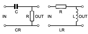
Fig.8.4.1 The Differentiator Circuit
A simple RC network such as the high pass filter illustrated in Fig. 8.4.1, when used with non sinusoidal waves produces a change in wave shape at its output. With a sine wave input, only the amplitude and phase of the wave change. However, if the input wave is a complex wave, such as a square or triangular wave, the effect of these simple circuits appears to be quite different.
Differentiation

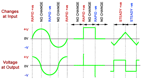
Fig 8.4.2 Differentiation.
The circuit is called a DIFFERENTIATOR because its effect is very similar to the mathematical function of differentiation, which means (mathematically) finding a value that depends on the RATE OF CHANGE of some quantity. The output wave of a DIFFERENTIATOR CIRCUIT is ideally a graph of the rate of change of the voltage at its input. Fig. 8.4.2 shows how the output of a differentiator relates to the rate of change of its input, and that actually the actions of the high pass filter and the differentiator are the same.
Because the differentiator output is effectively a graph showing the rate of change of the input, whenever the input is changing rapidly, a large voltage is produced at the output. The polarity of the output voltage depends on whether the input is changing in a positive or a negative DIRECTION.
Sine Waves
A graph of the rate of change of a sine wave is another sine wave that has undergone a 90° phase shift (with the output wave leading the input wave).
Square Waves
The square wave input and output in Fig 8.4.2 shows the ideal differentiator action of a high pass filter. The output wave is now nothing like the input wave, but consists of narrow positive and negative spikes. The positive spike coincides in time with the rising edge of the input square wave. The negative spike of the output wave coincides with the falling, or negative going (towards zero volts) edge of the square wave. Notice that the DC level of the wave is also changed by the differentiator. The output wave now has both positive and negative half cycles above and below a centre line of zero volts, due to the dc blocking effect of the capacitor.
Triangular Waves
A triangular wave has a steady positive going rate of change as the input voltage rises, so produces a steady positive voltage at the output. As the input voltage falls at a steady rate of change, a steady negative voltage appears at the output. The graph of the rate of change of a triangular wave is therefore a square wave. Wave shaping using a simple high pass filter or differentiator is a very widely used technique, used in many different electronic circuits.
Practical Differentiation

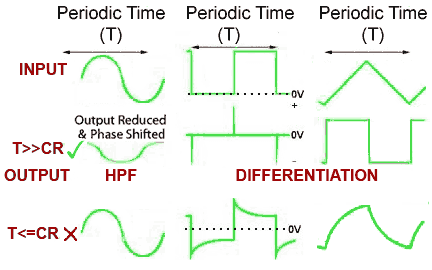
Fig 8.4.3 Practical Differentiation.
Although the ideal situation is shown in Fig. 8.4.2, how closely the output resembles perfect differentiation depends on the frequency (and therefore periodic time) of the input wave and the time constant of the components used, as shown in Fig. 8.4.3. The high pass filter works as a differentiator when the input is:
a. A non-sinusoidal wave.
b. The time constant(T) of the input wave is much greater (longer duration) than the time constant(CR) of the circuit (T>>CR), i.e. at relatively low frequencies.
When T is less than or equal to CR (T<=CR) the output wave shape will be less than an ideally differentiated wave shape, being more or less like the waveforms shown in the bottom row of Fig. 8.4.3.
Although passive (with no amplification) differentiators are cheap and efficient, where it is necessary to control the amplitude of the output, active differentiators using op-amps, as described in Amplifiers Module 6.6 are often used.


