Google Ads
Module 8.5
Integrators
- After studying Module 8.5 you should be able to describe:
- The effects of integration on sine waves and complex waves.
- • Sine waves.
- • Square waves.
- • Triangular waves.

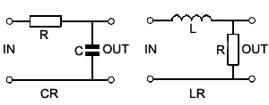
Fig. 8.5.1 The Integrator (also low-pass filter) Circuit.
The Integrator Circuit
Integration is used extensively in electronics to convert square waves into triangular waveforms, in doing this it has the opposite effect to differentiation (described in Filters & Wave shaping Module 8.4). The shape of the input wave of an integrator circuit in this case will be a graph of the rate of change of the output wave as can be seen by comparing the square wave input and output waveforms in Fig. 8.5.2. Notice that the integrator circuit (shown in Fig. 8.5.1) is that of the CR low pass filter described in Filters & Wave shaping Module 8.2.
Integrator Action with a Sine Wave Input

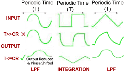
Fig. 8.5.2 Integrator Action
If the input is a sine wave, the circuit does not act as an integrator, but as a simple low pass filter (LPF) where the amplitude of the output wave is reduced, and its phase relative to the input wave is shifted so that it lags by up to -90° dependant on the frequency of the wave and the CR time constant of the circuit, as described in Filters & Wave shaping Module 8.2
The low pass filter circuit is therefore called an integrator only when:
a. The input wave is a square wave.
b. The periodic time(T) of the input wave is much shorter than the circuit time constant(CR) i.e.(T<=CR).
Provided that these conditions are met, then the action of the integrator is opposite to that of the differentiator circuit described in Filters and Wave shaping Module 8.4.
Integration of a Square Wave
With a square wave input and the correct relationship between the periodic time of the wave and the time constant of the circuit, Fig 8.5.2 shows that integration takes place. The output is now (considering the waveforms as simple graphs), a graph of the changing area beneath the input wave. The integrator has converted the square wave input to a triangular wave at the output, the slope of this wave describes the increase in area beneath the square wave (moving from left to right). For the circuit to act effectively as an integrator, the periodic time of the wave must be similar to, or shorter than the circuit time constant i.e. (T<=CR). The higher the frequency of the input wave for a particular time constant, the better the shape of the output wave will be, but the smaller its amplitude. Also notice that, unlike the differentiator, the integrator does not block any DC component of the input wave. Therefore the reduced amplitude output wave will have a DC component, which (igoring the resistance of any load placed on the output) will be the same as the average DC level of the input wave.
At lower frequencies, where the periodic time T of the wave is much longer than the time constant of the circuit CR (T>>CR), some change in wave shape does occur, but the output does not conform to the definition of an integrator; the circuit has just rounded the rapid vertical transitions of the square wave. The output at these low frequencies is not a graph of the changing area beneath the input wave, the circuit is acting as a low pass filter and removing the high frequency components of the square wave that were responsible for the rapid vertical changes at each half cycle.
Action on a Triangular Wave
When the input to the integrator circuit is a triangular wave, the output seems to become a sine wave. Remember however, that the integrator circuit is also a low pass filter that has the effect of removing the higher frequency harmonics present in the complex (triangular) wave at its input, leaving just the fundamental (sine wave) and possibly a few lower frequency harmonics. At low frequencies, the output from the integrator circuit is therefore a rounded form of the triangular input wave.
The main purpose of a passive CR integrator is to produce a good triangular wave shape from a square wave input, which it can do very well and at very low cost (only two components are needed) although the output will be reduced in amplitude. Any lack of amplitude may be overcome by combining the passive CR circuits described in this module with an op-amp to create an active filter, differentiator or integrator as described in Amplifiers Module 6.6.


