Module 4.1
Circuits & Resistors
- After studying this section, you should be able to:
- Label EMF(E) potential difference(p.d.) and Voltage(V) in a circuit diagram.
- Describe the difference between electron flow & conventional current.
- Define the Ampere.
Current, Voltage & E.M.F.
Electric Current
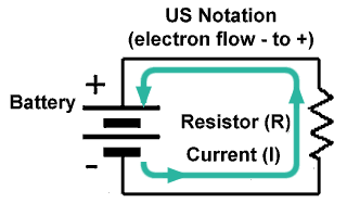
Electric current is the flow of electrons in a conductor. A conductor can be any material (usually a metal) that has an atomic structure that allows electrons to be easily detached from their parent atom by an electric force (called a voltage or an electric potential). These "free electrons", which are naturally negatively charged are attracted towards a positive electric charge. This movement is called ELECTRON FLOW and is also called an electric current. So current flows from the negative terminal to the positive terminal in an electrical circuit.
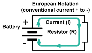
Looking at this a different way, the atoms that are now short of the negatively charged electrons that have been attracted away by the electric potential, must be positively charged. In this state they are called positive ions and they will be attracted towards a negative electric charge. Therefore current (in the form of positive ions) can also be considered to be flowing from positive to negative.
Therefore it depends whether current is considered to be due to the movement of electrons or to the movement of positive ions. Both are correct and both ways of considering current can be used in practice.

Fig. 4.1.1 Current Flow (US Method)

Fig. 4.1.2 Current Flow (EU Method)
To clarify which current flow is being referred to, the two directions of flow are called:
CONVENTIONAL CURRENT − Flows from positive to negative.
ELECTRON FLOW − Flows from negative to positive.
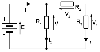
Whether current is considered as flowing from negative to positive or from positive to negative depends in many cases on where you live. In the USA some text books and diagrams may show current flowing from negative to positive (Electron Flow) although Conventional Current Flow is also used. In Europe Conventional Current flow is the preferred direction, unless specifically relating to the flow of electrons. Which system is used doesn´t really matter, so long as you know which system you are using! For most purposes at www.learnabout-electronics.org CONVENTIONAL CURRENT will be used for our explanations of how circuits work, only using electron flow when the flow of current is entirely, or mostly made up of moving electrons. (As in devices such as transistors). Therefore, unless specifically stated otherwise you can assume that current flows from positive to negative. This flow is normally shown in diagrams by a small arrow head placed on the conductor and labelled I1, I2 etc. as illustrated in Fig. 4.1.3.
Indicating Current Flow in a Simple circuit
Current is measured in Amperes, (often abbreviated as ‘Amps’) or commonly in milliAmperes or microAmperes in electronic circuits.
An Ampere can be defined as;
The amount of electric charge, measured in Coulombs, which passes a given point in a circuit, per second.
1 Ampere = 1 Coulomb per second.
1 Coulomb is the amount of charge carried by approximately 6.24150948 x 10¹⁸ electrons, or to be a little more exact: 6,241,509,479,607,717,888 electrons!
The measurement of the Ampere is not made, believe it or not, by sitting there and counting electrons! It is actually defined by calculating the force exerted between the magnetic fields around two parallel wires. If you are really keen to get into the numbers and method of defining the Ampere try this link to NIST, the National Institute for Standards and Technology at the U.S. Department of Commerce.
Voltage and E.M.F.

Fig. 4.1.3 Labelling Voltages and Currents.
Whenever a current is flowing, a voltage must be present. Voltage is sometimes described as an electrical pressure, the force that drives current through the circuit, just as water pressure drives water around a circulating pipe. In electrical terms, a voltage is actually the difference in electric charge at two points in a circuit. This difference in charge at two points will always try and equalise by causing the electrons to flow around the circuit. With no potential difference between different points in a circuit there will be no current flow. Equally if there are potential differences, but the circuit is incomplete (i.e. there is a break in the circuit) there will be no current.
What causes the charge difference is therefore the force that drives a circuit. This may be a device such as a CELL or a BATTERY (a battery is just several interconnected cells) or alternatively the source of electric potential may be derived from the mains (line) supply. Whatever the source of energy used the driving force for the circuit current can be called the ELECTRO-MOTIVE FORCE or E.M.F.
The term E.M.F. is only used to describe that difference in charge or difference in ‘voltage’ that is the actual source of power for our circuit. Differences in voltage between any other points in the circuit are called "potential differences" (abbreviated to p.d). Both EMF and potential difference are measured in Volts, and so are often both (inaccurately) called "voltages". In addition voltages may each sometimes be labelled E just to add to the confusion.
Strictly speaking the Electrical potential that drives the circuit is called an EMF (measured in volts) and is labelled E.
The difference in electric potential between any other two points in the circuit is called a POTENTIAL DIFFERENCE or p.d. (also measured in Volts) and labelled V.
A voltage in a circuit (either EMF or potential difference) may be shown by an arrow alongside the two points in the circuit (often the two ends of a component) where the potential difference or EMF exists. Conventionally the arrow head is at the more positive potential. Multiple voltages and currents may be labelled V1, V2, I1, I2 etc. as shown in Fig.4.1.3.


