
Google Ads
Module 4.3
Open Circuit Faults
- After studying this section, you should be able to:
- Describe the effects of open circuit components in basic resistive circuits.
- Diagnose open circuit component faults in resistive circuits.
Open Circuits
Current will only flow IN A CIRCUIT. That is, around a continuous path (or multiple paths) from and back to the source of EMF. Any interruption in the circuit, such as an open switch, a break in the wiring, or a component such as a resistor that has changed its resistance to an extremely high value will cause current to cease. The EMF will still be present, but voltages and currents around the circuit will have changed or ceased altogether. The open switch or the fault has caused what is commonly called an OPEN CIRCUIT.
Remember that wherever an open circuit exists, although voltage may be present there will be no current flow through the open circuit section of the circuit. Also, as Power(P) is V x I and the current (I) = 0, no power will be dissipated.
Looking further at the simple circuit Fig. 4.1 3 used in Resistors & Circuits Module 4.1 let´s put some actual voltages and currents in and see what happens under ‘Open Circuit’ conditions.
Use the animated version of Fig 4.1.3 below, (now called Fig 4.3.1) to select a number of open circuit conditions that might occur in different parts of the circuit. Notice how the voltages and currents around the circuit change depending on where the break in the circuit (the open circuit) occurs. Checking the voltages around a circuit with a voltmeter, and noticing where they differ from what would be expected in a correctly working circuit, is one of the main techniques used for tracing a fault in any circuit. Making sense of this method depends on understanding a few basic facts about the circuit:
- The current IS supplied to the circuit by the battery (E) is divided into two currents I1 flowing through R1 and I2 flowing through R2 and R3.
- Because R2 and R3 are connected in series, the same current (I2) flows through both resistors.
- Both branches of the circuit (R1 and R2/R3 have the same resistance in this circuit (150Ω, commonly shown in circuit diagrams as 150R).
- Therefore half of the 40mA supply current (20mA) flows through each 150Ω branch of the circuit, causing the shown voltages to be developed across each resistor.
It would be unusual in practice to be given all of the current and voltage information on every circuit diagram. The voltages and currents would need to be worked out where needed by applying the methods described in our section on Current and Voltage in Series and Parallel Resistor Networks.
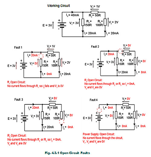
Fault finding techniques vary with the complexity of the circuit involved but all rely to some degree on the basic methods shown here, and very often on the application of Ohms Law. These examples, whilst not intended to be typical of faults encountered in already built printed circuits, may often be encountered when building circuits on breadboard (Proto board) when components may be wrongly inserted, or not make a good connection.
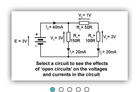
Fig.4.3.1 Open Circuit Examples.
The opposite extreme fault condition to having an open circuit is having a component or components go ‘Short Circuit’, which is dealt with Resistors & Circuits Module 4.4
Google Ads