Module 3.1
Phase Shift Oscillators
- After Studying this section, you should be able to:
- • Understand the operation of a Phase Shift Oscillator.
- • Describe the effects of using multiple filters on the frequency of oscillation.
- • Know relevant formulae for the frequency of oscillation.
- • Describe the advantages of buffered phase shift oscillators.
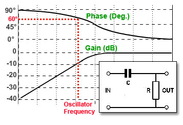
Fig. 3.1.1 High Pass Filter
The Phase Shift Network
This circuit uses the property of RC filters to cause a phase shift, and by using multiple filters, a feedback circuit with exactly 180° phase shift can be produced. When used with a common emitter amplifier, which also has a phase shift of 180° between base and collector, the filters produce positive feedback to cause oscillation to take place. The RC network commonly used is that of a high pass filter, (Fig. 3.1.1) which produces a phase shift of between 0° and 90° depending on the frequency of the signal used, although low pass filters can also be used.

Fig. 3.1.2 Three Cascaded High Pass Filters
If a number of identical filters are used in cascade, with the output of one filter feeding the input of the next, as shown in Fig. 3.1.2 a total phase shift of exactly 180° will be produced at one particular frequency. Usually three filters are used with each filter producing a phase shift of 60° at the required frequency.
As any single high pass filter can produce a phase change of up to 90°, it would seem that, in theory, only two such networks, would be needed. However, using two filters with each producing a 90°phase shift would mean that, as the phase graph in Fig. 3.1.1 shows, the phase response curve is quite flat at and above 90°, so any drift in frequency would have little effect on the 180° phase shift produced. This would mean that if the frequency of the oscillator changes, due to a change in temperature for example, there would be hardly any change in the amount of phase shift, so frequency stability would be poor. It can be seen from Fig. 3.1.1 that at 60° or 45° the phase response curve is much steeper, and so with three filters producing 60° each, or four filters providing 45° each, to make up the required 180°, frequency stability will be much better.
Using multiple filters in this way does create other problems however. The frequency of oscillation can be worked out by a fairly simple formula,

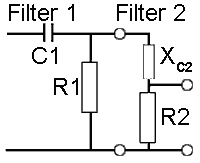
Fig. 3.1.3 Loading Effect
But because this formula is based on calculations for individual filters, it does not fully take into account the effect of connecting the filters in cascade, which causes of one filter to be 'loaded' by the input impedance of the next, as shown in Fig.3.1.3, where the input impedance of filter 2, made up of the reactance (XC) of C2 and the resistance of R2 effectively changes the value of the output resistor of filter 1 (R1) as they are effectively connected in parallel with it. Changing the output impedance of the filters in this way causes the frequency at which the filter produces the required phase shift to change, so altering the oscillator frequency. The more filters that are cascaded the worse the effect becomes, also making it more complex to accurately calculate the frequency of the phase shift oscillator.
In addition to the loading effect caused by the cascaded filters, the input impedance of the amplifier also contributes to the overall loading on the phase shift network. This loading caused by the amplifier can be minimised however, by ensuring that the amplifier has as high an input impedance as possible, for example using an op-amp instead of a BJT amplifier.
Due to the loading effect caused by the use of multiple filters and the added complexity of an additional filter, the four-filter 45° phase shift model is seldom used, even though using four filters does give slightly better frequency stability. Also the poor frequency stability of the two-filter model makes the three-filter oscillator the most usual choice.
RC Phase Shift Oscillator Using a Bipolar Transistor
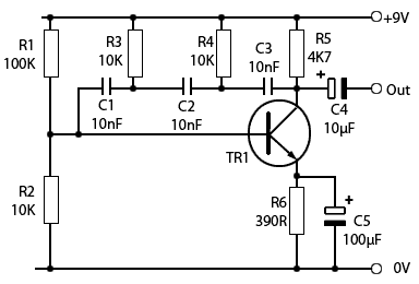
Fig. 3.1.4 BJT Phase Shift Oscillator
The circuit shown in Fig. 3.1.4 uses three high pass filters (C3/R4, C2/R3 and C1/R2) to produce 180° phase shift. A sine wave of approximately 3Vpp with minimum distortion is produced across the load resistor R5. The frequency of oscillation is given by:

In several tested practical examples of this circuit, the actual frequency produced was within 7% of the calculated value.
The basic BJT phase shift oscillator is a useful as a source of low frequency sine waves but does have a number of drawbacks:
•There can be quite a wide difference between the calculated frequency value and the actual frequency produced.
•The waveform amplitude is generally not well stabilised so a good wave shape is not guaranteed without additional circuitry.
•They are difficult to design in variable frequency form as this would involve ganging together either 3 variable capacitors or 3 large variable resistors, and such components are not readily available.
Buffered Phase Shift Oscillator
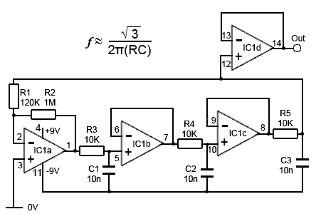
Fig. 3.1.5 Op Amp Buffered Phase Shift Oscillator
An improvement on the standard BJT version of the phase shift oscillator is obtained by using op amp buffers to reduce the loading on the phase shift filter circuits.
The circuit shown in Fig. 3.1.5, based on a design in the excellent “Op Amps for Everyone” Design Reference from Texas Instruments, uses one section (IC1a) of a quad Op Amp package for an amplifier with a gain of just over 8 (R2 ÷ R1) to replace the 1/8 losses in the three filters.
IC1 b and c provide non-inverting buffers (each with a gain of 1) so that the filters R3/C1 and R4/C2 are loaded only by the extremely high impedance of the op amp input. While the output of the circuit could be taken from the junction of R5/C3, this point has a high impedance and is therefore not able to drive any low impedance load.
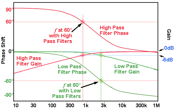
Fig. 3.1.6 Comparison of 60° Frequencies in
High & Low Pass Filters
However the fourth section of the quad op amp (IC1d), is not required as part of the oscillator, and can therefore be used as a ‘no extra cost’ output buffer amplifier, providing a low impedance output. This enables the oscillator to easily drive other circuits or such devices as a small loudspeaker.
Notice that this design uses low pass, rather than the high pass filters that are common in BJT phase shift oscillator designs.
Because the 60° phase shift point in a low pass filter occurs at a different frequency to that in a high pass filter (see Fig. 3.1.6) the frequency of oscillation is higher, around 2.76kHz with low pass filters compared with about 690Hz when high pass filters are used. Fig. 3.1.6 also shows that the gain of an individual filter (high or low pass) is -6dB, which is equivalent to 0.5 in voltage gain, which (being less than 1) is a loss. Therefore the three low pass filters in Fig. 3.1.5 will contribute a total loss of 0.5 x 0.5 x 0.5 = 0.125 or 1/8th, meaning that for a closed loop gain of 1 the amplifier will need a gain of 8.
To make sure the oscillator starts up however, a slightly higher gain is needed, so the gain of IC1a is set by R1 and R2 as 1M/120k = 8.33. This is considerably lower than the gain of 29 required for the BJT version in Fig.3.1.4.
In Fig. 3.1.5 there is virtually no loading of the filter circuits, due to the presence of the op amp buffers. Because the frequency of oscillation of the buffered amplifier shown in Fig. 5 is higher than that in Fig.3.1.4, due to its use of low pass filters, the frequency of oscillation for Fig. 3.1.4 and Fig. 3.1.5 must be calculated differently.
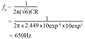
Although both oscillators use the same values for R and C (10KΩ & 10nF), the BJT version shown in Fig. 3.1.4 has its frequency is calculated as:
However, because the op amp version in Fig. 3.1.5 uses low pass filters, a change in formula is needed:
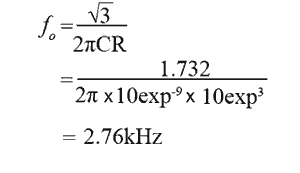
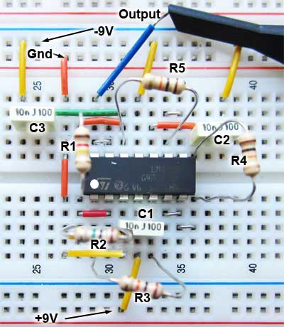
Fig. 3.1.7 Buffered Phase Shift
Oscillator on Breadboard
The loading effect, or lack of it can also affect the frequency, changing the actual frequency of a practical phase shift oscillator from the calculated value, theoretically by as much as 25% in BJT circuits.
However, when the two oscillators described here were tested, the error between the calculated and actual frequency in both cases was less than 7%; within the error range expected due to component tolerances, this is another problem that is greater with phase shift oscillators than LC oscillators, due to the increased number of components (three RC pairs controlling the frequency instead of just one LC pair in LC oscillators).


