Module 3.2
BJT Phase Shift Oscillator Practical Project
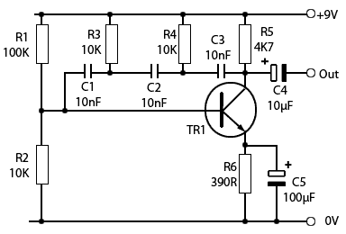
Fig. 3.2.1 Phase Shift Oscillator
- After Studying this section, you should be able to:
- • Build a Phase Shift Oscillator from given instructions.
- • Test a Phase Shift Oscillator for correct operation.
- • Take measurements on a Phase Shift Oscillator.
Building a Phase Shift Oscillator
Try this circuit out for yourself; download full constructional details to build the phase shift oscillator shown in Fig 3.2.1 using either breadboard (proto board) or strip board, then test the oscillator’s operation using a multi-meter and oscilloscope. A really effective way to learn about oscillators!
This Phase Shift oscillator produces a sine wave output in excess of 3Vpp at an approximate frequency set by the values chosen for the filter components. Other values may be used to vary the frequency obtained.
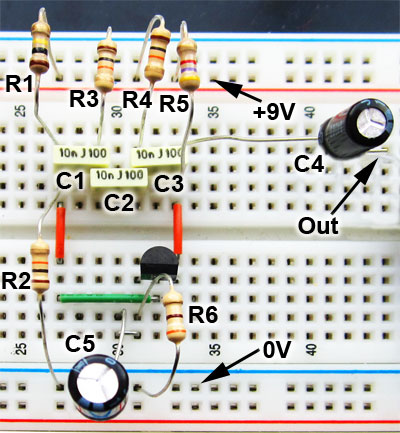
Fig. 3.2.2 Phase Shift Oscillator
Breadboard Version
The circuit will operate from a 9V battery, or a DC power supply of 9 to 12V. Supply current at 9V is less than 1mA.
The circuit can be built on breadboard as shown in Fig 3.2.2 for testing purposes. To make the amplifier gain variable, R6 can optionally be replaced by a 1K variable resistor. This can be adjusted to find the value that gives the best wave shape and reliable amplitude.
Construction on Breadboard
Components List.
- TR1 = 2N3904
- C1, C2 & C3 = 10nF
- C4 = 10μF
- C5 = 100μF
- R1 = 100K
- R2, R3 & R4 = 10K
- R5 = 4K7
- R6 = 390R
Additional Components For Stripboard Version
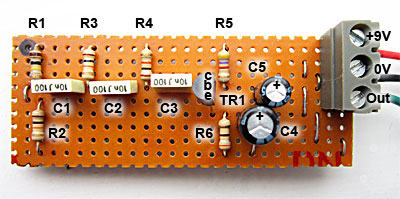
Fig. 3.2.3 Phase Shift Oscillator
Stripboard Version
- Strip board 9x25 holes
- 3 way connection block (Optional)
- 9V battery connector (Optional)
- Tinned copper wire (for links)
- Insulated flexible wire(for external connections)
Construction - Stripboard Version
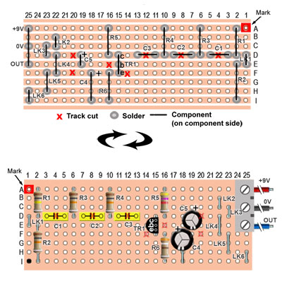
Fig. 3.2.4 Phase Shift Oscillator
Layout on Stripboard
- On a piece of 9 x 25 hole strip board, mark hole A1 on both sides of the board as shown in Fig. 3.2.4 to ensure that counting the strips and holes for placing track cuts and components always starts from the same point.
- Mark the holes where track cuts are to be made. Double check their correct position before cutting.
- Make the track cuts.
- Solder the wire links in place.
- Solder the components in place in the following order.
- Resistors.
- Polyester capacitors.
- Transistor (check for correct e b c positions before soldering).
- Electrolytic capacitors, (check for correct polarity before soldering).
- Terminal Block.
Carefully check for any short circuits made by solder bridging adjacent tracks, and for any poorly soldered joints.
Connect up the power supply, and connect an oscilloscope to the output.
Once the circuit is oscillating reliably, carry out the tests indicated on the Phase Shift Oscillator Measurements Test Sheet.
BJT Phase Shift Oscillator Measurements
Having built the phase shift oscillator, either on breadboard or strip board, check that the circuit is oscillating satisfactorily by displaying the output waveform on an oscilloscope.
1. Calculate the design frequency of the oscillator using: ƒo = 1/2π(√6)CR = ______________Hz.
2. Using a multi-meter, take the DC measurements and complete Table A.
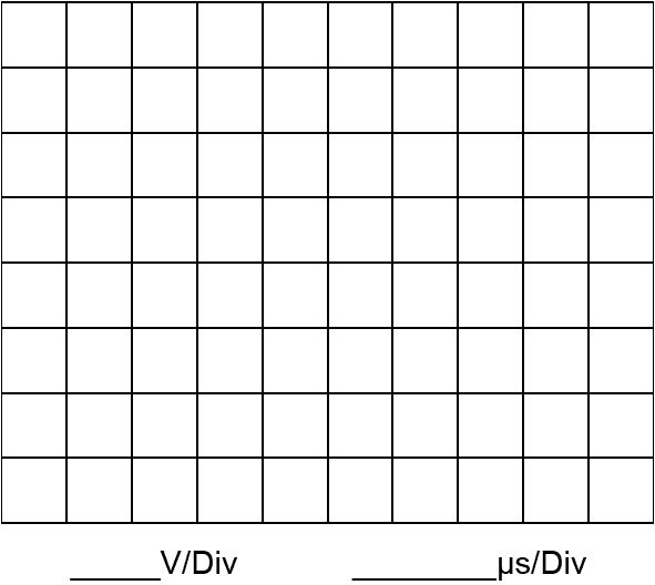
3. With an oscilloscope connected to TR1 collector (not the circuit output terminal) draw at least two cycles of the collector waveform on the grid below. Enter the time/division and volts/division settings of the CRO in the spaces provided.
4. From the waveform, calculate and record the values in Table B.
| Table A | |
|---|---|
| The supply voltage | |
| The supply current | |
| TR1 collector voltage | |
| TR1 base voltage | |
| TR1 emitter voltage | |
| Table B | |
|---|---|
| Peak to Peak Voltage | |
| DC level of the wave | |
| Periodic time T of the wave | |
| Frequency of the wave (1/T) | |
