Module 3.3
The Wien Bridge
- After Studying this section, you should be able to:
- • Understand the operation of the Wien Bridge Circuit.
- • Calculate the frequency of a wien bridge oscillator.
- • Understand the relationship between gain and phase in a wien bridge oscillator.
- • Recognise the need for gain control.
The Wien Bridge Circuit
For frequencies much below 1MHz RC oscillators become more practical than LC types because of the physical size and expense of the inductors and capacitors required at low frequencies. A problem arises with RC oscillators however, when a variable frequency is required.
In LC oscillators a single tuned circuit controls the frequency, which can be changed simply by making either a single inductor or a single capacitor variable. The frequency of oscillation in RC types, such as the phase shift oscillator, is controlled using multiple RC combinations to produce the correct amount of phase shift at the required frequency.
To alter the frequency, it is therefore necessary to alter the value of at least three components, either resistors or capacitors simultaneously. Even though it is possible to manufacture ganged variable capacitors, the size of capacitors needed at low (e.g. audio) frequencies means that the capacitors would have to be physically too large to be practicable.
It is also possible to manufacture multiple variable resistors but much more difficult to ensure that the tracking of such components is accurate enough, i.e. as the resistance of the multiple resistors is varied, they must each change their resistance at exactly the same rate. Again the cost of suitable components becomes impractical for many purposes.
In addition, it is possible to build Wien Bridge oscillators having very low levels of distortion compared with Phase Shift designs.
The Wien Bridge
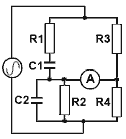
Fig. 3.3.1 The Wien Bridge
The original Wien Bridge circuit shown in Fig. 3.3.1 was developed in 1891 for the purpose of accurately measuring capacitor values. To find the unknown value of C1 for example, when the other component values are known, an AC signal is applied across the circuit and the value of another component (e.g. R1) is varied by a calibrated potentiometer. At some point, the bridge will ‘balance’ when the ratio of resistances in the R3/R4 arm matches the ratio of impedances in the two halves of the arm including C1, R1, C2 and R2. This will be indicated by both sides of the ammeter ‘bridge’ being at the same potential so the meter indicates zero current. At this point it is possible to calculate the value of the unknown capacitor C1.
A second use for the Wien Bridge is to measure an unknown frequency. If all the component values are known, the same bridge balancing procedure can be used to measure, by calculation, the frequency of the AC supplied.
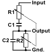
Fig. 3.3.2b The Wien Bridge with
Frequency Control
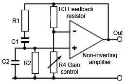
Fig. 3.3.2a The Basic Wien Bridge Oscillator
When the Wien Bridge is used in an oscillator R1 C1 and R2 C2 control the frequency, the other resistors (R3 and R4 in the bridge circuit of Fig. 3.3.1) are replaced by the feedback resistor (R3) and gain control (R4) of a non-inverting amplifier as shown in Fig.3.3.2a. The advantage of using this circuit in a Wien Bridge oscillator is that frequency can now be easily controlled by replacing R1 and R2 with a two section variable resistor as shown in Fig. 3.3.2b.
The section of circuit shown in Fig. 3.3.2b is effectively two RC filters, high pass and low pass, where R1=R2 and C1=C2. The combined action of these filters is to form a band pass filter having a high impedance at one particular frequency that can be calculated by the formula:

Example (R = 100KΩ C= 1nF):
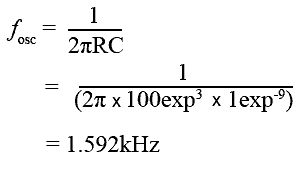
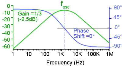
Fig. 3.3.3 Gain & Phase Response of a Wien Bridge Network
As can be seen from the response curve of the filter in Fig. 3.3.3, the filter is also a phase control network. There is a sharp change in the phase relationship between input and output around the frequency of oscillation ( ƒosc). At ƒosc however, maximum gain (shown in green) and zero phase shift (shown in blue) coincide.
As the phase shift network is part of the positive feedback loop of a non-inverting amplifier, the result will be that positive feedback will occur only at the frequency of oscillation (ƒosc). The conditions for oscillation in any oscillator are that there must be positive feedback, and a closed loop gain of 1.
Notice that the filter gain at ƒosc is –9.5dB or 1/3, therefore to give a closed loop gain of 1 the non-inverting amplifier will have to have a gain of 3. With the correct gain and zero degrees phase shift the circuit will therefore oscillate. However for oscillations to start at switch on, there must be some noise present at ƒosc (not a problem as any amplifier will have some noise present over a wide spectrum of frequency) and the initial gain will need to be slightly higher than 3.
The Wien Bridge oscillator produces a sine wave output with very low distortion, but if the amplifier’s closed loop gain remains greater than 1 (3 x 1/3) once the oscillator is running, the amplitude of the oscillations will keep increasing, driving the amplifier towards saturation and causing distortion. Clearly there is a need for some form of amplitude control if distortion is to be avoided.
Development of the Wien Bridge Oscillator
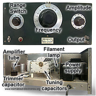
Fig. 3.3.4 The Hewlett Packard 200C Wien Bridge Audio Oscillator
Although the Wien Bridge had been around since 1891 it was not until 1939 that William Hewlett at Stanford University incorporated it into a practical audio frequency sine wave oscillator that has low distortion and a variable frequency and also a stable amplitude. This was achieved by the inclusion of an ordinary filament lamp to control the amplifier gain. In collaboration with fellow student David Packard, the firm of Hewlett Packard was created to manufacture (initially in Dave Packard’s garage) a useful, inexpensive and highly successful audio signal generator.
Lamp circuit
The circuit developed by Bill Hewlett for his masters thesis at Stanford University introduced a self-varying amount of negative feedback into the circuit to automatically control the amplitude of oscillation, allowing an initial gain greater than 3 and then automatically reducing to exactly 3. The way he achieved this was to include a simple (and cheap) filament lamp in the bias circuit of the tube (valve) amplifier, which can be seen in the rear view of the HP200C signal generator shown in Fig. 3.3.4. Notice that in this version the tuning is carried out by a bank of four large variable capacitors rather than resistors.


