Module 7.2
Meters for Transistor Testing.
- Section 7.2 Meters for Transistor Testing
- • Typical Transistor Faults.
- • Digital and Analogue Multimeters.
- • Available test features.
- • Checking meter polarity.
Typical Transistor Faults.

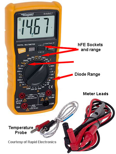
Fig. 7.2.1 Digital Multi-meter with
semiconductor testing features.
When a transistor fails one of two things usually happens:
- 1. A junction goes ‘short circuit’ (A junction resistance becomes very low or zero Ohms).
- 2. A junction goes ‘open circuit’ (A junction resistance becomes very high or infinity).
On rare occasions a junction may become ‘leaky’ (slightly low resistance) though this is rare. In practice such a fault is usually followed fairly soon by a complete short circuit.
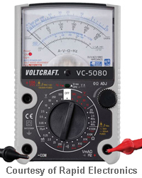
The most common methods for testing transistors therefore consist of basic resistance checks. A particular sequence of resistance measurements can be used to show that the transistor is either good or faulty. Although different types of transistor (e.g. BJT, JFET, or MOSFET) require different test sequences, any of the tests can be carried out using a fairly inexpensive basic multi-meter, and this can be either digital or analogue. Two typical examples are shown in Fig.7.2.1. and Fig.7.2.2
Digital and Analogue Multimeters
The digital meter shown in Fig. 7.2.1 also has useful additional ranges for testing temperature and hFE (current gain), useful for further tests but not essential for the ‘go/no go’ tests that are more commonly needed.

Fig.7.2.2 Analogue Multi-meter.
The analogue meter has a really useful display that displays the required results at a glance (the deflection of the meter needle) rather than having to read and calculate the value shown in figures on the digital meter. However when using an analogue meter, not all meters behave in the same way. On older analogue meters it is possible that the polarity of the testing voltage on the positive and negative test leads is reversed when using the resistance ranges, red = negative and black = positive. However on modern analogue multi-meters this is not necessarily so, therefore before starting any semiconductor fault finding be sure which polarity your meter uses.
Checking the Polarity of Analogue Multimeters
A simple test to confirm the polarity is to measure the forward and reverse resistances of a known good diode. With your meter set to a low (x1 or x10) resistance range or the diode range if the meter has one, the forward resistance reading across the diode (red lead connected to anode and black lead to cathode) should be lower than the resistance readin obtained when the red lead is connected to the cathode and black to anode. If this is true, the polarity of the voltage used by the meter to measure resistances is not reversed, (red lead is positive and black lead is negative). Typical readings in this test using a good diode would be forward resistance about mid range on the meter and reverse resistance will be infinity, (no movement of the needle) .


