
Google Ads
Module 2.8
Testing Diodes
- After studying this section, you should be able to:
- • Describe methods for testing diodes using digital or analogue multi-meters
- • Recognise typical faults in diodes.
- • Open Circuit.
- • Short Circuit.
- • Leaky.
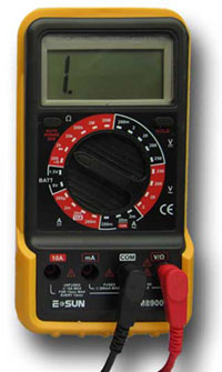
Fig. 2.8.1 Digital Meter
Multimeter Diode Testing
Diodes can be tested using a multi meter. It is normally the resistance of the diode in both forward and reverse directions that is tested. There are however a number of points to remember when testing diodes.
With Digital Meters
Most digital multi-meters are suitable for diode testing, and in many cases will have a special ‘diode test’ range usually marked with a diode symbol. This range should always be used when testing diodes or any other semiconductor device. The reason for this is that the meter tests the diode by applying a voltage across the diode junction. The normal voltages used by the meter on other resistance ranges may not be high enough to overcome the diode´s forward junction potential and so will not make the diode conduct, even in the forward direction. This would give an indication that the diode was open circuit (very high resistance). If the diode range is used, the test voltage applied by the meter will be high enough in most cases to overcome the forward junction potential and the diode will conduct. Therefore in the forward direction (meter positive lead to the diode anode, and the negative lead to the cathode) the diode's resistance can be measured.
The actual value of resistance will depend on the slope of the forward characteristic of the diode at the voltage applied by the meter, and so will vary from device to device and from meter to meter, so a precise value cannot be given. When measuring a good silicon diode (not connected to any circuit), a reading in the forward direction of about 500Ω to 1kΩ could be expected, similar or slightly less with germanium diodes. With the meter leads reversed, an out of range (infinity) or open circuit reading (usually indicated by a display something like ‘1.’ on a digital meter, as shown in Fig. 2.8.1) should be expected.
If the diode is already in a circuit, the resistances measured, always with the circuit switched off, will be affected by any parallel paths. Therefore readings will be lower than those indicated above. However very low or zero ohm readings may indicate a short circuit diode (the most common fault with diodes) making it worthwhile, if no other obvious reason for the very low reading can be seen, to remove at least one end of the diode from the circuit and re-check the diode's forward and reverse resistance.
With Analogue Meters
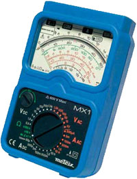
Fig. 2.8.2 Analogue Meter
If an analogue meter is used for testing it must be remembered that because zero on the resistance and voltage scales are reversed, due to the inner workings of the meter, the polarity of the probes when using analogue meters for resistance measurement, is also reversed compared to digital meters. Therefore when measuring resistance of a diode with an analogue meter on any range the BLACK lead is positive and the RED lead is negative. This means that the black lead should be connected to the anode and red to cathode to measure the FORWARD resistance of the diode. Some analogue meters have a specific diode testing range, but most analogue meters will be quite suitable for diode testing. The most suitable analogue range will normally be indicated in the user instructions, but as with digital meters the actual voltage used on the testing range should be checked to to understand its effect on the expected forward and reverse resistances.
NOTE: the above paragraph refers only to true analogue meters, many modern "analogue" models tend to be digital meters with an analogue display. In this case the method described for digital meters should be followed. Which meter is yours? A simple resistance test on a known good diode can be used; connect the black -ve lead to the cathode and the red +ve lead to the anode. If the meter shows the expected forward resistance the meter lead polarity is not reversed.
It is also quite usual for the forward resistance measurement across some LEDs, especially those such as blue LEDs that have a higher forward junction potential to appear to very high (infinity) during testing if the meter voltage on the diode range is low, even when the LED is OK. However a meter with a test voltage of around 3V should produce some glow from the LED. Some multi-meters are also available, which instead of displaying the resistance of the diode on the diode test range, display the junction potential (in volts). It is therefore essential to make sure you know what conditions the meter uses before testing any semiconductors.
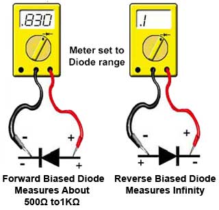
Fig. 2.8.3 Connecting a Digital Meter
for Testing a Diode
Making the tests
The diagram below shows how to connect a digital meter to test the diode. There are a number of things to remember:
- • Make sure you are using the diode range.
- • Using a digital meter, connect the black lead to the cathode and red to the anode (forward bias - around 1kΩ).
- • Reverse the meter connections (reverse bias - infinity reading).
REMEMBER - If you are using an analogue meter to measure resistance the polarities of the test leads are reversed.
SOME METERS, when measuring diode resistance, give a reading indicating the junction potential (in volts) instead of the diode's resistance (in Ohms) CHECK YOUR METER INSTRUCTIONS so that you are sure what the meter reading indicates.
Identifying Diode Connections
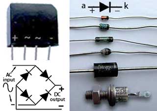
Fig. 2.8.4 Diode Polarity Markings.
The cathode connection of a diode is marked in various ways. In the case of a bridge rectifier package, the AC input terminals and the DC output terminals are usually marked with a sine wave symbol and plus/minus signs respectively, as shown.
Bridge rectifiers can be tested as ordinary diodes as long as each diode is tested separately. The package pins should be compared with the diagram of the internal layout of the four diodes as shown in Fig. 2.8.4 so you can test each diode´s forward and reverse resistance. Single diodes are generally marked with a band to indicate the cathode, but with stud type rectifiers there is generally a diode symbol printed on the case.
Fault Indications
Short Circuit
Diodes can be damaged by high voltages, especially diodes working in high voltage or high power applications such as power supplies, and as a result will usually go short circuit 0Ω when measured in either direction. When a diode in a power supply goes short circuit, large currents can flow and obvious damage occurs such as "cooked" diodes and / or blown fuses. Short circuit diodes that are not obviously damaged show 0Ω or very low resistance in both forward and reverse directions.
Open Circuit
Occasionally, diodes (especially small signal diodes) may go open circuit, and read very high resistance or infinity (shown as 1 on digital meters) in both forward and reverse directions.
Leaky
Sometimes a signal diode may become "leaky". While its forward resistance may be normal, its reverse resistance may be lower than the expected infinity. This type of fault is usually restricted to small signal diodes, since if power diodes become leaky, the extra reverse current flow will almost certainly generate enough heat to rapidly destroy the diode. In small signal diodes this fault can only be reliably measured with the diode removed from the circuit because of the parallel resistances of any other components connected across the diode will tend to produce lower than expected reverse resistance.
Testing Zener Diodes
All Zener diodes have a defined voltage, and if the voltage measured across them under working conditions, is higher than that printed in the circuit manual (or on the diode if you can see the markings), then the diode is faulty, (probably open circuit) and must be changed. Zener diodes exhibit similar short and open circuit faults to other diodes, but in addition may become ‘noisy’. The normally very stable voltage across them suffers from very rapid fluctuations similar constant to the ‘background noise’ hiss on a poor audio signal. As Zener diodes are often used to stabilise power supply lines, this rapid fluctuation of voltage can give rise to strange faults, depending on what is being supplied by the power supply in question. The moral is - If a circuit is behaving strangely, and noise on the power supply is suspected, check any Zener diode stabilising that line by substituting it with a known good diode.
Testing LEDs
LED testing is described in Diodes Module 2.5