Module 5.1
Phase shift in AC Components
- After studying this section, you should be able to describe:
- • Phase Shift in Common AC Components.

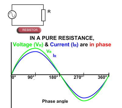
Fig. 5.1.1 Resistance in AC Circuits
Resistance in AC Circuits
In purely resistive circuits, the current and voltage both change in the same way, and at the same time, as described in Module 4.1. This relationship is true, whether the applied voltage is direct or alternating. The main difference in AC circuits is that the voltage continues to change in a way that depends on the shape of the input wave. When a sine wave voltage is applied to a purely resistive circuit, it produces a sine wave (sinusoidal) current. Both waveforms attain their peak values at the same time, and pass through zero at the same time. Voltage and current in a purely resistive circuit are therefore said to be "IN PHASE" with each other.

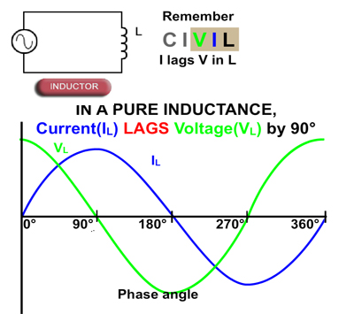
Fig. 5.1.2 Inductance in AC Circuits
Inductance in AC Circuits
In a purely inductive circuit the voltage and current waveforms are not in phase. Inductance opposes change in current due to the back emf effect. This causes the current to reach its peak value some time after the voltage. So in an inductive circuit, current "LAGS" voltage.
In DC circuits the current eventually settles to a steady state value, and the period of change prior to steady state depends on the time constant (i.e. the component values) of the circuit. In an AC circuit however, as the voltage is continually changing, the current also continues to change, and in a purely inductive circuit, the peak values of current occur a quarter of a cycle (90°) after those of the voltage.
In a circuit containing both inductance and resistance, which is usually the case as the inductor (a coil of wire) will have some internal resistance, the current will lag the voltage by an amount between practically 0° (nearly pure resistance) and almost −90° (nearly pure inductance). Since voltage and current no longer rise and fall together, a "PHASE SHIFT" is occurring in the circuit.

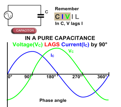
Fig. 5.1.3 Capacitance in AC Circuits
Capacitance in AC Circuits
Capacitance has the property of delaying changes in voltage as described in Module 4.3. That is, the applied voltage reaches steady state only after a time dictated by the time constant. In AC circuits voltage and current are changing continuously, and in a purely capacitive AC circuit the peak value of the voltage waveform occurs a quarter of a cycle after the peak value of the current. Therefore a phase shift is occurring in the capacitor, the amount of phase shift between voltage and current is +90° for a purely capacitive circuit, with the current LEADING the voltage. The opposite phase shift to an inductive circuit.
A very CIVIL relationship
One way to memorise these current/voltage (I/V) relationships in capacitors(C) and inductors (L) is to consider the positions of letters in the word CIVIL. The first three letters CIV indicate that in a capacitor (C), V lags (comes after) I, and the last three letters VIL indicate that I lags (comes after) V in an inductor (L).


