Google Ads
Module 10.1
Ideal Parallel Circuits
- After studying this section, you should be able to:
- • Recognise ideal LCR parallel circuits.
- • Describe the effects of internal resistance.

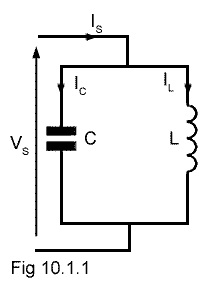
Fig. 10.1.1 The "Ideal" LC Parallel Circuit
The circuit in Fig 10.1.1 is an "Ideal" LC circuit consisting of only an inductor L and a capacitor C connected in parallel. Ideal circuits exist in theory only of course, but their use makes understanding of basic concepts (hopefully) easier. It allows consideration of the effects of L and C, ignoring any circuit resistance that would be present in a practical circuit.
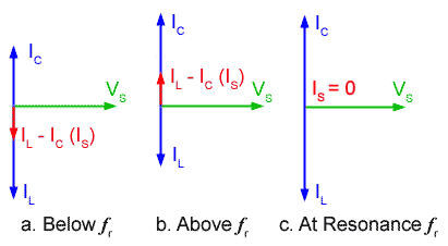
Fig 10.1.2 shows phasor diagrams for the circuit in Fig 10.1.1 under three different conditions, below, above and at resonance. Unlike the phasor diagrams for series circuits, these diagrams have a voltage VS as the reference (horizontal) phasor, and have several phasors depicting currents. This is because, in a parallel circuit the voltage VS is common to both the L and C arms of the circuit but each of the component arms (L and C) can have individual CURRENTS.
The phasors for L and C seem to be reversed compared with the phasor diagrams for series circuits in module 9, but the parallel phasor diagram shows the current IC through the capacitor leading the supply voltage VS by 90°, while the inductive current IL lags the supply voltage by 90°. (The mnemonic CIVIL introduced in Module 5.1 still works for these diagrams.)

Fig. 10.1.2 Phasor diagrams for the Ideal LC Parallel Circuit
The supply current IS will be the phasor sum of IC and IL but as, in the ideal circuit, there is no resistance present, IC and IL are exactly in antiphase, and IS will be simply the difference between them.
Fig 10.1.2a shows the circuit operating at some frequency below resonance ƒr where IL is greater than IC and the total current through the circuit IS is given by IL − IC and will be in phase with IL, and it will be lagging the supply voltage by 90°. Therefore at frequencies below ƒr more current flows through L than through C and so the parallel circuit acts as an INDUCTOR.
Fig 10.1.2b shows the conditions when the circuit is operating above ƒr. Here, because XC will be lower than XL more current will flow through C. IC is therefore greater than IL and as a result, the total circuit current IS can be given as IL − IC but this time IS is in phase with IC. The circuit is now acting as a CAPACITOR.
Notice that in both of the above cases the parallel circuit seems to act in the opposite manner to the series circuit described in AC Theory Module 9.1. The series circuit behaved like a capacitor below resonance and an inductor above. The parallel circuit is acting like an inductor below resonance and a capacitor above. This change is because the parallel circuit action is considered in terms of current through the reactances, instead of voltage across the reactances as in the series circuit.
At resonance (ƒr) shown in Fig 10.1.2c, the reactances of C and L will be equal, so an equal amount of current flows in each arm of the circuit, (IC = IL). This produces a very strange condition. Considerable current is flowing in each arm of the circuit, but the supply current is ZERO! There is no phasor for IS! This impossible state of affairs of having currents flowing around the circuit with no supply current, indicates that the circuit must have infinite impedance to the supply. As there is no resistance in either L or C in the ideal circuit, current continues to flow from L to C and back again. This only happens of course in an ideal circuit, due to the complete absence of resistance in either arm of the circuit, but it is surprisingly close to what actually happens in a practical circuit, because current is in effect "stored" within the parallel circuit at resonance, without being released to the outside world. For this reason the circuit is sometimes also called a "tank circuit".


