Google Ads
Module 10.3
Parallel Resonance
- After studying this section, you should be able to:
- • Describe the action of LCR parallel circuits above, below and at resonance.
- • Describe current magnification, and dynamic resistance in LCR parallel circuits
- • Use appropriate formulae to carry out calculations on LCR parallel circuits, involving resonance, impedance and dynamic resistance.
Just as in series resonant circuits, there are three basic conditions in a parallel circuit. Dependent on frequency and component values, the circuit will be operating below, above or at resonance. This section describes these three conditions using phasor diagrams involving the current phasors IC, IL and their phasor sum IS, with the reference phasor VS. Note that VR is not shown, but its presence in the circuit is indicated by the variable angle of IL as described in Module 10.2.
Below Resonance
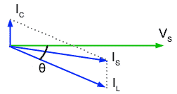
Fig. 10.3.1 Below Resonance
Firstly, if the supply frequency is low, below the resonant frequency ƒr then the condition shown in Fig 10.3.1 exists, and the current IL through L will be large (due to its comparatively low reactance). At the same time the current IC through C will be comparatively small. Because IC is smaller than IL the phase angle θ will be small. Including IS in the diagram shows that it will be lagging on VS and therefore the circuit will appear to be INDUCTIVE. (Note that this is the opposite state of affairs to the series circuit, which is capacitive below resonance).
Above Resonance
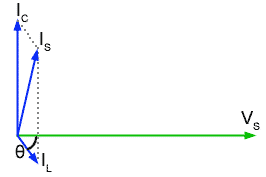
Fig 10.3.2 Above Resonance
Fig 10.3.2 shows what happens at frequencies above resonance. Here the current IC through C will be greater than the current IL through L, because the frequency is higher and XC is smaller than XL, θ is greater than in Fig 10.3.1. This gives us the condition where IS (the phasor sum of IC and IL) is leading VS and so the circuit is capacitive.
At Resonance
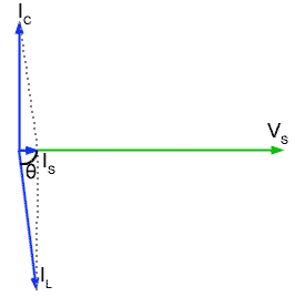
Fig 10.3.3 At Resonance
At resonance the ideal circuit has infinite impedance, but this is not quite the case in practical parallel circuits, although very nearly. Fig 10.3.3 shows the conditions for resonance in a practical parallel LCR circuit. IC is leading VS by 90° but IL is not quite in anti phase (due to the resistance in the circuit´s inductive branch). In the parallel circuit therefore, resonance must be defined as the frequency where the values of IC and IL are such that IS is IN PHASE with VS.
Dynamic Resistance
At resonance, Fig 10.3.3 (above) shows that IS is very small, much smaller than either IC or IL so the impedance across the parallel circuit must be very high at ƒr and as IS is in phase with VS, the circuit impedance is purely resistive. This pure resistance that occurs only at ƒr is called the DYNAMIC RESISTANCE (RD) of the circuit and it can be calculated (in ohms) for any parallel circuit from just the component values used, using the formula:

Where R is the total resistance of the circuit, including the internal resistance of L.
Current Magnification
The other important point shown in Fig 10.3.3 is the size of the phasor for IS compared with IC and IL. The supply current is much smaller than either of the currents in the L or C branches of the circuit. This must mean that more current is flowing within the circuit than is actually being supplied to it!
This condition is real and is known as CURRENT MAGNIFICATION. Just as voltage magnification took place in series circuits, so the parallel LCR circuit will magnify current. The MAGNIFICATION FACTOR (Q) of a parallel circuit can be found using the same formula as for series circuits, namely;

Adjusting for resonance.
The formula for the resonant frequency of a LCR parallel circuit also uses the same formula for ƒr as in a series circuit, that is;

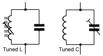
Fig 10.3.4 Parallel LC Tuned Circuits.
But it should be noted that this formula ignores the effect of R in slightly shifting the phase of IL. In fact the formula only gives an approximate value for ƒr. However, because the internal resistance of L is usually quite small, so is its effect in shifting the resonant frequency of the circuit. For this reason, the same formula may be used for ƒr in both series and parallel circuits. In those practical LC circuits designed to operate at high frequencies, and where accurate control over ƒr is required, it is normal for either L or C to be made adjustable in value.
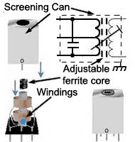
Fig 10.3.5 Tuned Transformer in a screening can
The final values for L and C would be achieved by adjusting one of the two components as shown in Fig. 10.3.4 which would be of a variable type, once the system containing the LC circuit was operating. By this method, not only is the effect of R compensated for, but also any stray inductance or capacitance in the circuit that may also affect the final value of ƒr. Because, at high frequencies, magnetic fields easily radiate from one component in a circuit to another, LC tuned circuits would also be shielded (screened) by containing them in a metal screening can as shown in Fig 10.3.5.
6 Things you need to know about LCR Parallel Circuits.
(and that are different to the Series Circuit.)
- 1. AT RESONANCE (ƒr) VC is not necessarily exactly equal to VL but VS and IS are IN PHASE
- 2.; AT RESONANCE (ƒr) Impedance (Z) is at maximum and is called the Dynamic Resistance (RD)
- 3. AT RESONANCE (ƒr) Circuit current (IS) is at a minimum.
- 4. AT RESONANCE (ƒr) The circuit is entirely resistive.
- 5. BELOW RESONANCE (ƒr) The circuit is inductive.
- 6. ABOVE RESONANCE (ƒr) The circuit is capacitive.


