Google Ads
Module 11.3
Power Transformers.
- After studying this section, you should be able to describe:
- • Tappings.
- • Laminated and Toroidal Core Power Transformers.
- • Isolation.
- • Autotransformers.
- • Switch Mode Power Supply Transformers.
- • Transformer Faults.
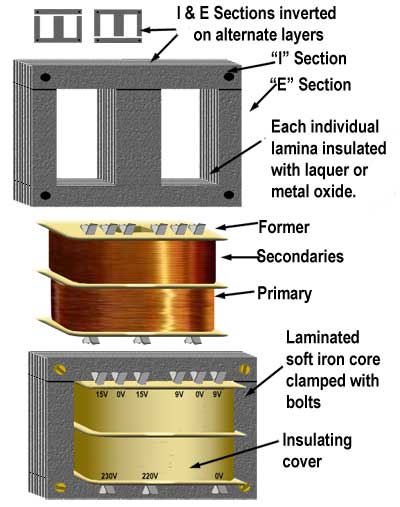
Fig. 11.3.1 Laminated Core Power Transformer.
Laminated Core Power Transformers
The job of a Power Transformer in an electronic system is to provide that system with a number of AC supplies of various voltages and suitable values of current, from the high voltage public electricity supply. In addition it may be required to provide electrical isolation between the electronic circuitry and the external public power supply. A typical power transformer construction using a laminated core is shown in Fig 11.3.1
A core of thin steel ‘E’ and ‘I’ shaped laminations is used to reduce the effects of eddy currents. These are clamped together and the primary and secondary windings wound on a former placed around the central limb of the core. The windings may be separate as shown, or often, for greater efficiency, wound concentrically in layers (primary, secondary, primary, secondary, etc). Transformers are often made specific to a particular application or equipment in which they are used. Correct identification of windings may therefore require reference to manufacturers data.
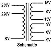
Fig. 11.3.2 Schematic Diagram of a
Tapped Power Transformer.
Tappings.
To enable transformers to supply a range of secondary voltages to different parts of a circuit it is common for power transformers to have "Tapped windings". That is, windings split into various sections by using a number of connections brought out from a single winding, each one at a particular number of turns along the winding, as shown in the schematic symbol diagram Fig 11.3.2 below.
This provides a selection of different turns ratios between primary and secondary allowing different input voltages to be used and a range of different output voltages to be obtained.
By using a winding with a central tapping, e.g. 9V 0V 9V, a balanced supply can be provided giving two equal voltages (9V) of opposite polarity, or a single 18V supply.
Toroidal Power Transformers
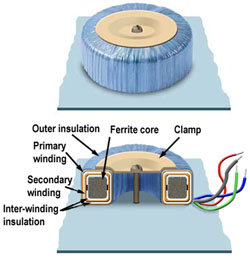
Fig 11.3.3 Toroidal Power Transformer
A popular design for power transformers is based on the toroidal core shown in Fig 11.3.3, (A toroid is simply a do-nut shaped core). This design gives excellent linkage between primary and secondary as both coils are wound on top of each other around the same core, rather than the separate windings used on E-I transformer cores. Eddy current losses in the toroidal core are kept low by either making the core from a spiral strip of grain oriented steel or molding the core from high permeability ferrite core material. The toroidal transformer construction, although generally more expensive than E-I shaped laminated steel core types, the toroidal core provides a smaller and lighter transformer than for a given power rating, together with higher efficiency and less leakage of magnetic field around the transformer.
Isolation.
One advantage of transformers (except for Autotransformers) is that there is no electrical connection between the input circuit connected to the primary and the output circuit connected to the secondary; they can therefore be used to electrically isolate two circuits.
Mains (Line) Isolation Transformers are used to give greater safety to users of electrical equipment such as outdoor power tools, and to technicians servicing equipment where live conductors and components may be touched, by providing input and output terminals that are electrically isolated from the main circuit.
Large isolating transformers are typically capable of handling a power output of about 250-500 VA (volt amperes) without being overloaded. Their primary is connected directly to the mains supply, and to give a mains (or line) output voltage their turns ratio is 1:1 as illustrated in Fig. 11.3.4. They also have an earthed metal shield between primary and secondary windings to prevent AC being passed by electrostatic (capacitive) as well as inductive coupling between the two windings.

Fig. 11.3.4 Mains Isolation Transformer.
The use of an isolation transformer greatly reduces the risk of a shock to a person simultaneously touching a live conductor and earth, as the secondary circuit has no earth connection and therefore no continuous circuit for current to flow. The isolation transformer does NOT prevent shock to anyone touching live and neutral at the same time.
Much smaller isolating transformers are used in voice and data communication equipment such as Fax machines and modems, where their task is to safely isolate equipment that may, under fault conditions, allow high voltages to be present at their interface with the public telephone system. They are also used to match the impedance of the equipment inputs and outputs to those of the telephone lines.
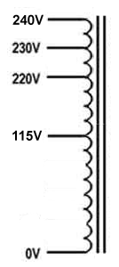
Fig. 11.3.5 Schematic diagram of
an Autotransformer.
Autotransformers.
This is a special type of transformer that has only one winding. It is often used for conversion between different mains (line) voltages, allowing electrical equipment to be used internationally. The single continuous winding is divided into a number of "tappings" as shown in Fig. 11.3.5 to produce different voltages. An appropriate number of turns are provided between each tapping to produce the required voltage, based on the turns ratio between the complete winding and the tapping. A useful method of calculating unknown voltages on an autotransformer, if the number of turns on the various tappings are known, is to use the volts per turn method described on the Basic Transformer Operation page. Unlike a conventional transformer with primary and secondary windings, the autotransformer does not provide any isolation between input and output.
Autotransformers are also used to provide the very high voltages need for such applications as automobile ignition systems and cathode ray tube drives in CRT TVs and monitors.
The "Auto" part of the name in this case does not mean automatic but has the meaning of "One – acting on its own" as in autonomous.
Switch Mode Power Supply Transformers
Large laminated core transformers are less common nowadays because of the use of Switch Mode Power Supplies (SMPS). These circuits operate at much higher frequencies than the older 50-60Hz supplies. In addition to being more efficient SMPS have the advantage that many of the components in the power supply circuit can be physically much smaller and lighter, including the transformer. SMPS transformers, working at around 500kHz,like the example in Fig 11.3.6 in a TV receiver, use ferrite instead of laminated cores as losses in the ferrite are much less at high frequencies than in laminated cores. The waveforms handled by transformers in SMPS, in addition to being high frequency, generally have a square wave shape. Because of this, they will contain many harmonics at even higher frequencies. This creates a problem due to 'skin effect'; high frequency currents flowing in wires tend to flow only along the outer skin of the wires, which makes the normal calculations of wire cross sectional area more complex. Because the effective cross sectional area changes with frequency, then so will the effective inductance of the winding. Also, the layout of components in relation to SMPS transformers needs careful design, as electromagnetic interference at high frequencies is greater.
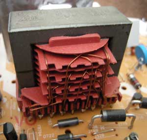
Fig. 11.3.6 Switch Mode Power Supply
Transformer.
Transformer Faults
Transformers are generally highly reliable; their very high efficiency means that under normal conditions little power is dissipated as heat (in many components the biggest killer!). As with any electronic device, it is those that handle the greatest power that are the least reliable, so power transformers, especially those operating with high voltages that are more susceptible than other transformer types, to breakdown.
Overheating, whether caused by an internal fault, or by overloading can lead to dangerous, even complete "meltdown" situations. For this reason many power transformers may be fitted with a temperature operated fuse or cut–out. In the unlikely advent of this device failing it is usual that the primary winding will appear to be open circuit. It is often difficult or impossible to remove and or repair the fuse, which will be buried deep within the windings. It is also very possibly unwise to do so, as the transformer will have overheated for one of two probable reasons:
- 1. The transformer has been seriously overloaded for some considerable time; in which case internal damage to the insulation may have occurred. The safest option is to replace the transformer.
- 2. The transformer has suffered an internal shorted turn. This means that the insulation between two turns of a winding has broken down. The effect of this is to create a winding of a single turn. The transformation ratio is now enormous! Imagine a transformer with a 1000 turns on its primary and 100 turns on it secondary, suffering a shorted turn on the secondary winding. The turns ratio has just changed from 10:1 to 1000:1! The result is very little secondary voltage but enormous current. In this case again the only solution is replacement.
The only fault I personally encountered with any regularity over 26 years of electronics servicing was insulation breakdown on very high voltage transformers; the type used to generate several thousand volts in TV receivers. Most of these faults occurred on Saturday afternoons during the summer, the reason? People returning from vacation often did so on Saturday afternoon, and the TV had been unused for a week or more. During that time damp had penetrated the transformer windings and when high voltage was applied once more,arcing occured and the transformer immediately suffered a shorted turn.
With any fault where a transformer (whatever type) is suspected, the likelyhood of it being the culprit is very low down the list of probabilities.


