Google Ads
Module 11.4
Audio Transformers.
- After studying this section, you should be able to describe:
- • AF Transformers
- • Microphone Transformers.
- • Impedance Matching.
- • 100V Line Transformers.
AF Transformers.

Fig 11.4.1 Small audio transformer.
Audio Frequency (AF) Transformers work at frequencies between about 20Hz to 20kHz and are used in audio amplifier circuits, they were essential in valve (tube) designs for matching the high impedance outputs of theses amplifiers to low impedance loudspeakers, but transistor amplifiers have much less need for output transformers. AF transformers are still produced however for a range of audio functions; many are similar in construction to the power transformers described in Module 11.3, but are often much smaller, see Fig 11.4.1.
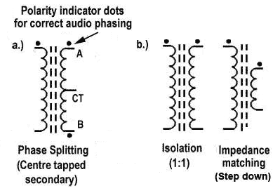
Fig 11.4.2 AF transformer schematic diagrams showing phase indicators.
Some common arrangements of audio transformer windings are shown in Fig 11.4.2.
Example a.) shows a centre tapped secondary winding that can be used to provide a selection of different turns ratios. Some transformers may also have tapped primaries for an even wider range of ratios. In audio amplifiers, the phase/anti phase of signals can be important and phase splitting transformers with centre tapped secondary windings can be used to provide two anti phase signals. The dots near the windings on schematic diagrams indicate the relative polarity of the signals on different windings, and in this example show that the signal from the upper secondary winding (A) will be in phase with the primary signal, while the lower secondary winding (B) will provide a signal in anti phase with the primary signal.
Example b.) shows two output transformers, used to couple the power output stage of an audio amplifier to the loudspeaker.
Audio transformers often perform several functions at once:
- Where used, they allow the AC audio signal to reach the loudspeaker whilst preventing any DC from the amplifier affecting the operation of the loudspeaker.
- They provide an isolated external connection for the loudspeakers, improving safety.
- They can match the low input impedance of the loudspeaker (typically a few ohms) to the much higher output impedance of an amplifier, allowing maximum power to be transferred from the amplifier to the speaker.
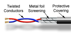
Fig. 11.4.3 Balanced Microphone Cable.
Microphone Transformers.
Audio transformers can also be used for matching microphones to amplifier inputs. The main purpose of a transformer at the amplifier input is matching impedance between microphones, connecting cables and the amplifier input. This is important to ensure that there is no signal reduction due to impedance mismatching.
To prevent electromagnetic interference, often in the form of a low frequency hum, long microphone cables usually use a balanced cable similar to that shown in Fig. 11.4.3. This consists of two conductors twisted together surrounded by a conducting shield made from metal foil or braid. Because the conductors are twisted together, effectively rotating their relative positions to each other, magnetic fields generated by each conductor into the other, tend to cancel out. The surrounding earthed conducting foil helps prevent external magnetic fields from affecting the conductors.
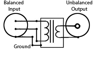
Fig. 11.4.4 A Balun.
A transformer with a single primary and a centre-tapped secondary is used to connect the microphone (a two wire unbalanced device) to the balanced cable. Because the cable is fed from a centre-tapped transformer, the signals on the two conductors are in anti-phase.
The amplifier input uses the difference between these two signals to produce a signal that is doubled in amplitude. Any noise that has been externally induced into the cable after the transformer will be identical in phase on both conductors, so the subtraction (difference) combination occurring at the amplifier input cancels out these noise signals.
The combination of signals at the amplifier can be carried out either by using a differential amplifier (an amplifier with two anti-phase inputs), or by using a balun (BALanced to UNbalanced) device. This is a type of transformer for matching balanced transmission lines or cables to, or from an unbalanced input or output, (the device is reversible). A simplified Schematic of a balun is shown in Fig. 11.4.4.
Fig. 11.4.5 shows a typical microphone transformer that plugs directly into an unbalanced high impedance amplifier input. The XLR socket at the other end of the device allows a low impedance microphone to be connected via a long lead. The transformer within the metal screening case acts as a balun, an impedance matching device and an input isolator for the microphone.
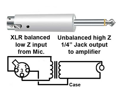
Fig. 11.4.5 A Microphone Matching Transformer.
Impedance Matching.
When the output of one circuit or device is feeding an AC signal to the input of another circuit or device, it is important that the input and output impedances are properly matched. In most cases impedance matching requires that the maximum VOLTAGE is transferred from one circuit or device to the next and for the transfer of maximum voltage this is achieved using simple resistance networks.
Where it is required to transfer the maximum amount of AC POWER between the circuits, transformers may be used. This is because a transformer has the ability to "transform" or change the apparent impedance of a circuit input or output. It can make a low impedance appear much higher, or a high impedance much lower.
Suppose a transformer has a primary to secondary ratio of 10:1 and a load impedance ZL of 8Ω is connected across the secondary winding. If 20 volts is applied to the primary winding the voltage across the load impedance will be:
20 × NS / NP = 20 (1/10) = 2volts
Therefore the current in the load impedance ZL will be:
IL = VL / ZL = 2/8 = 0.25 = 250mA
So the current in the primary must be 1/10 of this amount:
IP = 250mA × 0.1 = 25mA
Thus the apparent resistance of the primary winding must be:
RP = VP / IP = 20v / 25mA =800 ohms
Therefore the 10:1 transformer "magnifies" the impedance ZL of the load so that it appears to the amplifier as though it is feeding a load impedance of 800 ohms instead of the actual impedance of 8Ω. The apparent load on the amplifier has been increased in value by a factor of 100 times by the presence of the transformer. Notice the amount of the apparent increase; 100 times. As the turns ratio of the transformer is 10:1 the increase in apparent resistance (or impedance) is the square of the turns ratio. This relationship is described by the formula;
ZP = ZS (NP/NS)2
Ensuring that the output stage of an amplifier is correctly matched to its load.
100V Line Transformer.
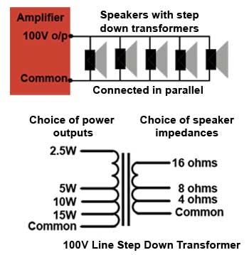
Fig. 11.4.6 100V Line Transformer.
Another Audio transformer, used for multi loudspeaker public address systems is the 100V line transformer used for connecting multiple speakers in public address systems to a single amplifier. The word "Line" in the title should not be confused with the United States public electricity supply. In the 100V line speaker system, a transformer steps up the audio output signal voltage to 100V so that the output current for a given power is low. The resistance on long cables between the amplifier and loudspeakers will attenuate this low current signal much less than if the current were left at its normally high level. An impedance matching step down transformer (shown in Fig. 11.4.6) is used at each speaker to reduce the voltage and increase the current again, and to match the line to the low impedance of the loudspeaker. The multiple connections on the primary allow suitable level of power (and therefore sound volume) to be chosen for each loudspeaker, and the secondary has a choice of impedances to match a range of loudspeakers.


